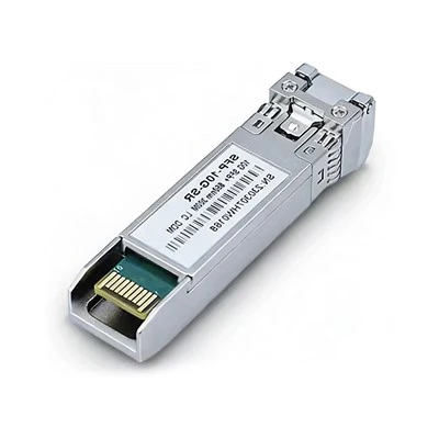

How Does A Fiber Optic Transceiver Work? A Chip-To-Connector Guide
Nov 12, 2026
Leave a message
TL;DR: How does a fiber optic transceiver work? It converts electrical data from your switch into laser light, sends that light down the fiber, and converts incoming light back into electrical data, both directions at once. The full answer, how does a fiber optic transceiver work from chip to connector, is a five-step chain: DSP, driver, laser, fiber, receiver. This guide breaks down every step, plus what's inside, model numbers, and DDM troubleshooting.
Quick answer: A fiber optic transceiver is a two-way translator between your switch and the fiber. The transmit side cleans the electrical signal with a DSP, then a laser diode writes the data onto a beam of light. The receive side catches that light with a photodetector and rebuilds clean electrical data. Both sides run at the same time inside one hot-swappable module.
How does a fiber optic transceiver work? In one sentence, it takes the electrical data coming out of your switch, turns it into pulses of laser light, sends those pulses down the fiber, and converts the light coming back into electrical data again. Both conversions run at the same time inside one thumb-sized metal module.
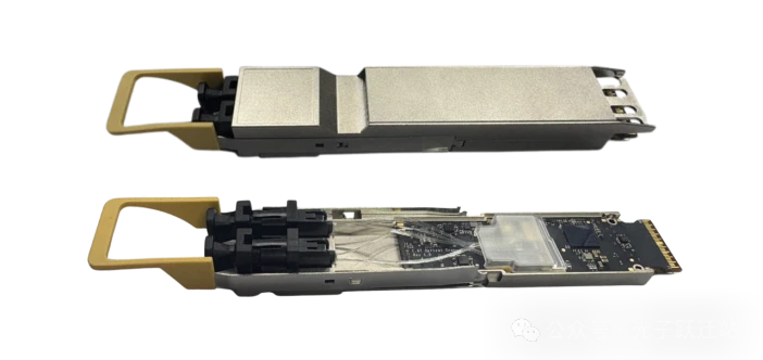
The numbers behind that sentence are the real story. One 800G module moves about 100 GB of data every second through eight lanes of light while drawing around 16 watts, about what a fast phone charger uses. Meanwhile, LightCounting's Ethernet optics forecast projects that optics for AI clusters alone could grow into a $100 billion a year market by 2030, so these little translators now sit at the center of the whole industry.
We have spent more than 20 years at COBTEL building the DFB and EML laser chips, the finished modules, and the MPO cords that connect them, all under one roof. So in this guide we open the box the way our engineers do: station by station, from chip to connector.
1. What Is a Fiber Optic Transceiver and What Does It Actually Do?
A fiber optic transceiver is a small, hot-swappable module that plugs into a switch, router, or server and converts data between electrical signals and light signals in both directions at once. The name joins "transmitter" and "receiver", because the module does both jobs inside one metal case.
Think of where it sits. Your switch has one big processing chip (engineers call it an ASIC) that speaks electricity. The outside world of long-distance links speaks light. The transceiver is the translator that lives between them, right at the port on the front of the switch. As TXO's beginner overview explains, the "transceiver" label simply reflects this double duty of sending and receiving in one package.
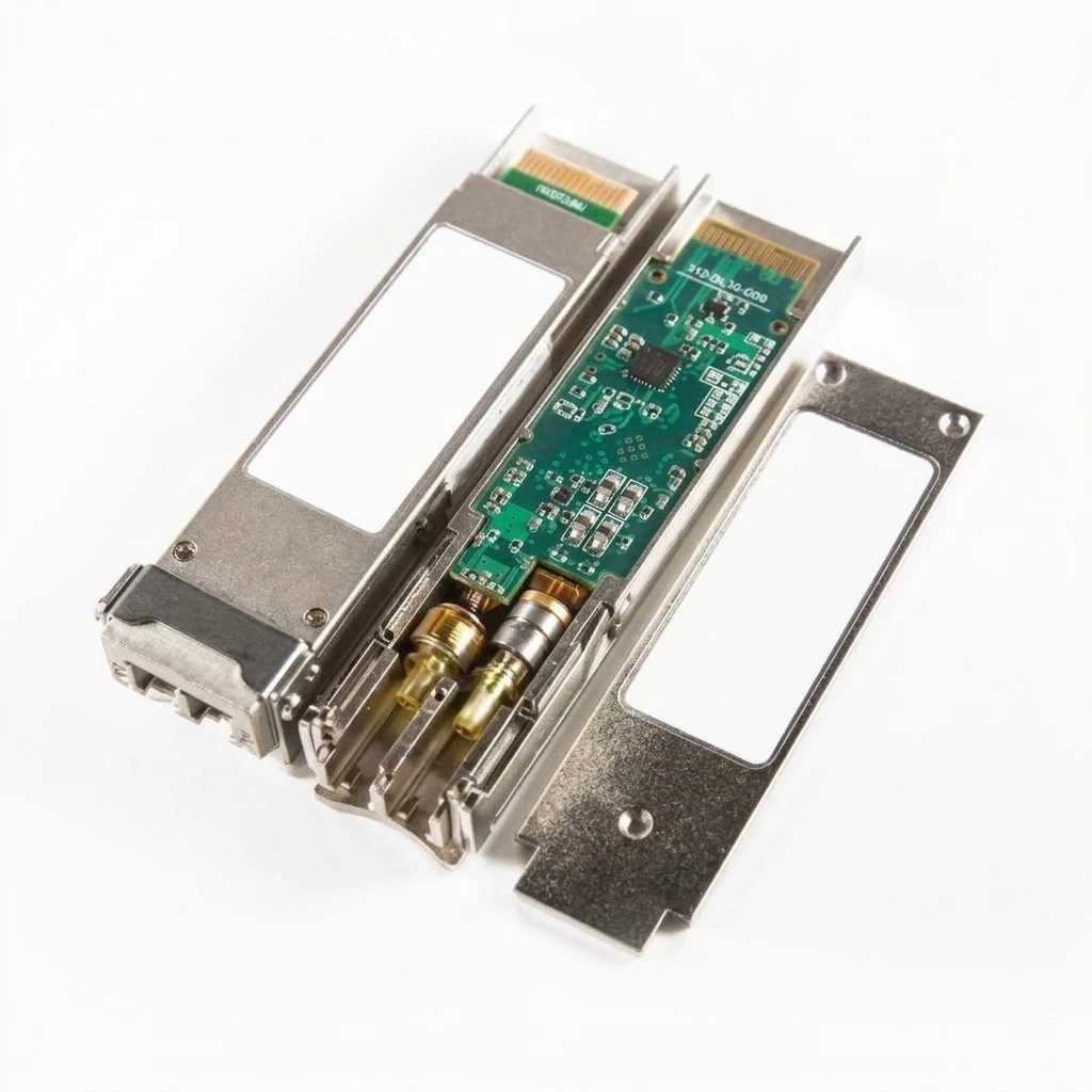
"Hot-swappable" means you can pull one out and plug a new one in while the switch stays powered. That small feature shapes the whole industry. Because modules follow shared industry sizes (MSA standards), you can upgrade a link from 10G to 100G by swapping a module, not the whole switch. If you want the catalog view of sizes and speeds, our optical module lineup covers the range from 1G to 800G, and our companion post explains what an optical module is in more basic terms.
Why bother with light at all? Electrical signals fade fast in copper, which is why copper links top out around 100 meters. Light in glass fades slowly and ignores electrical noise, so the same data can travel hundreds of meters to hundreds of kilometers. The transceiver makes that possible on both ends of every link.
2. How Does a Fiber Optic Transceiver Work, Step by Step?
On the transmit side, the module takes electrical data from the switch, cleans and reshapes it in a DSP chip, and uses it to drive a laser that writes the data onto light. On the receive side, a photodetector turns incoming light into tiny currents, an amplifier strengthens them, and a DSP restores clean data.
Let's follow one data packet on its journey. It enters the module through a row of gold fingers (the gold-plated contacts that slide into the switch cage). From there it passes through a chain of five stations before it leaves as light:
|
Station
|
Transmit side (your switch to fiber)
|
Receive side (fiber to your switch)
|
|
1. Host interface
|
Gold fingers carry data in from the switch chip
|
Restored data leaves through the same fingers
|
|
2. DSP / CDR chip
|
Times, reshapes, and maps the electrical signal
|
Recovers the clock, equalizes, and corrects errors
|
|
3. Analog chips
|
Driver pushes precise current into the laser
|
TIA turns the detector's tiny current into a real voltage
|
|
4. Optical engine
|
Laser (in the TOSA) writes data onto light
|
Photodiode (in the ROSA) turns light back into current
|
|
5. Optical port
|
Light exits through the LC or MPO connector
|
Light arrives from the far-end module
|
Two stations deserve a plain-language explanation, because they do the invisible work.
The CDR (clock and data recovery) chip solves a timing puzzle. High-speed data arrives as a stream of voltage changes with no separate wire saying "this is where each bit starts". The CDR watches the signal and rebuilds that timing information, so every later station knows exactly when to sample. Without it, the rest of the chain would read the data at the wrong moments and scramble it.
The laser stage is more subtle than "turn on, send 1, turn off, send 0". At multi-gigabit speeds, the laser is biased with a small continuous current so it stays warm and ready, then the driver modulates it around that point. The Fiber Optic Association's transmitter reference describes this bias-and-modulate scheme as the standard way lasers reach high speeds. A laser that fully switched off for every zero could not keep up.
The receive side runs the same chain in reverse. A photodiode catches the light and produces a current so small that engineers measure it in microamps. The TIA (transimpedance amplifier, a fast and sensitive amplifier) converts that current into a voltage the DSP can judge. The DSP then rebuilds clean data and hands it back to the switch. Our post on the main parts of an optical transceiver goes deeper on each component if you want the part-level view.
One last point: both directions run at the same time. In most links, two fibers carry the traffic, one for each direction, which engineers call full duplex. Some designs push both directions through one fiber on two different wavelengths. Either way, the module is always sending and receiving at once, and neither side waits for the other to finish.
The light itself also carries a quiet detail: its color. Multimode links usually run at 850 nm, while single-mode links use 1310 nm or 1550 nm, chosen to match how far and how fast the data must travel. You do not need to memorize the numbers, but you will see them printed on every label, and they matter when you pair modules with patch cords.
Video: FOA Lecture 27, Fiber Optic Data Links (12:41), by the Fiber Optic Association on YouTube. It walks through the same transmit, receive, and fiber chain described above.
3. What's Actually Inside the Module? A Layer-by-Layer Teardown
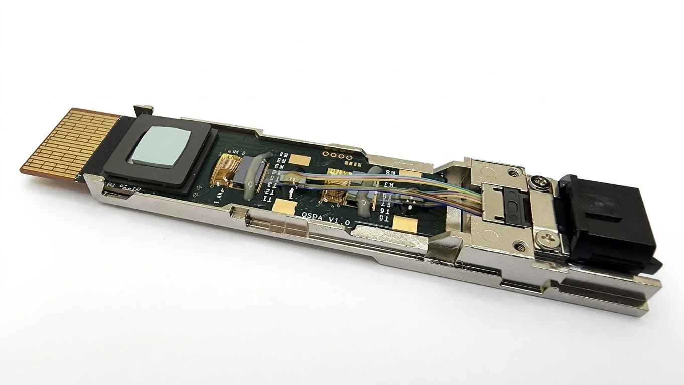
Inside the housing sit seven layers: a shielding shell, a high-speed PCB, a DSP or CDR chip, driver and amplifier chips, a transmit optical assembly, a receive optical assembly, and the optical interface with its lenses and LC or MPO connector. In 400G and 800G parts, these separate pieces merge into compact optical engines.
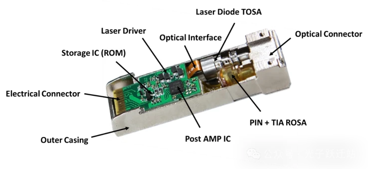
Open the shell (carefully, with the right tools) and here is what you meet, from outside in:
Metal shell and pull tab. It shields against electromagnetic noise, survives hot-plugging, and on 800G parts often carries fins or a spring pad to push heat into the switch's airflow.
High-speed PCB with gold fingers. This board carries the electrical lanes between the switch and the module's chips. At 800G, each lane runs at 112G or faster, so the board material and trace lengths matter as much as the chips.
DSP / CDR / gearbox chip. The signal repair station and the lane rearranger. It is usually the biggest power user inside the module.
Driver and amplifier chips. The laser driver on the transmit side, the TIA on the receive side.
Transmit optical assembly (TOSA). The laser chip plus its lens, packaged in a tiny metal can. The name you will see in datasheets is TOSA, which stands for transmit optical sub-assembly.
Receive optical assembly (ROSA). The photodiode plus its lens. Some designs combine both into one BOSA for bidirectional single-fiber links.
Optical interface. Lenses, alignment structures, and the fiber connector, LC for duplex links or MPO for parallel links. Precision here is brutal: the lens and fiber must line up with the laser chip within a few micrometers, or light is wasted.
The shell deserves more credit than it gets. It is not just a box: it blocks electromagnetic noise from the crowded switch chassis, holds every internal part in precise position through years of thermal cycles, and conducts heat out into the switch's airflow. On an 800G module, dropping the heat sink features would raise the laser's temperature enough to shift its wavelength and shorten its life.
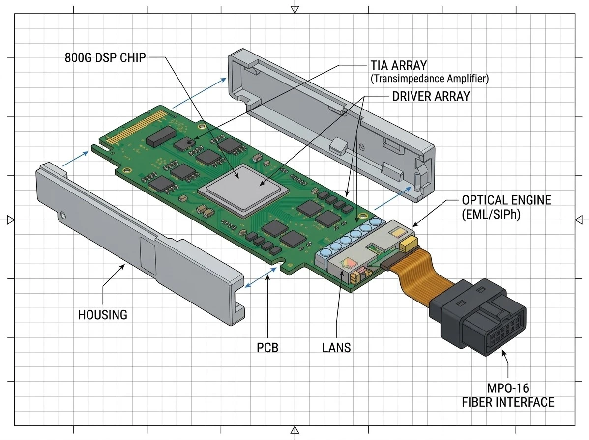
In low-speed SFP modules, that TOSA and ROSA sit as separate cylinder-shaped cans, and the block diagram matches the physical parts neatly. At 400G and 800G, the industry moved to arrays and integration: multi-channel laser arrays, silicon photonics chips, and "optical engines" that combine many functions in one block. The signal chain inside a transceiver is the same in principle, but the packaging has changed dramatically.
That seventh layer is why we care so much at the factory. A perfect laser behind a badly aligned lens is a bad module. Parallel links push this further: one MPO connector may carry 8 or 16 fibers at once, so every lane must align, not just one. Our MPO patch cords and fiber optic connectors are built and tested with exactly this interface in mind.
Video: Pluggable Optical Transceivers Explained (11:35), by FiberGuide on YouTube. It tours real modules and shows the form factors and internal parts covered in this section.
4. Which Laser Does the Work: VCSEL, DML, EML, or Silicon Photonics?
Short links over multimode fiber use cheap VCSELs at 850 nm. Medium and long single-mode links use DFB lasers (often called DMLs) or EMLs, which pair the laser with a built-in modulator for the highest speeds. Silicon photonics integrates the modulator on a chip and relies on a separate light source.
The laser is the part that sets your distance and speed limits, so it pays to know the four families:
|
Light source
|
Usual wavelength
|
Typical job
|
Where you meet it
|
|
VCSEL
|
850 nm
|
Cheap, fast, short reach
|
Server and storage links over multimode fiber, up to about 100 m
|
|
FP / DFB (DML)
|
1310 or 1550 nm
|
Directly modulated, low cost
|
1G to 100G single-mode links, up to tens of kilometers
|
|
EML
|
1310 or 1550 nm
|
Laser plus built-in modulator
|
100G and 200G per lane single-mode links, 500 m and beyond
|
|
Silicon photonics
|
External laser feeds the chip
|
Many optical functions on one chip
|
400G DR/FR classes and modern optical engines
|
A VCSEL emits light from the surface of the chip, which makes it cheap to make and test in volume, and it pairs with multimode fiber. A DFB laser etches a grating inside the chip to emit one precise wavelength, which is what single-mode links need. The Fiber Optic Association's source comparison shows the practical split: VCSELs own the 850 nm multimode world, while DFB lasers deliver narrow spectra for longer single-mode reach.
Here is the catch that decides everything at high speed. Directly modulating a laser (switching its current on and off) distorts the light as speeds climb. The FOA puts the practical ceiling for direct modulation at roughly 25 to 50 Gb/s per lane. Above that, you need an EML: a laser that stays steadily on, with a separate "shutter" chip (the modulator) flicking the beam instead. That separation keeps the light clean at 100G and 200G per lane.
That shutter trick also explains the price gap you see in catalogs. An EML is really two chips acting as one: the laser plus a fast modulator, aligned and packaged together. More chips and more alignment steps mean more places for production to add loss, which is why EML modules cost more than their DML cousins, and why chip screening matters so much at this level.
Which fiber the link uses is the other half of the decision, and our single mode vs multimode fiber guide covers that pairing in detail.
This is also where our own story becomes relevant. COBTEL designs and produces DFB and EML chips in-house, then packs them into modules in the same facility. When the chip and the module come from the same production line, the chip's behavior is known down to each wafer, not just to a datasheet average.
5. Why Is PAM4 the Secret Behind 400G, 800G, and 1.6T?
PAM4 is a modulation scheme that uses four light power levels instead of two, so one symbol carries two bits and the data rate doubles on the same laser and fiber. The levels sit close together, so a DSP must clean the signal to keep errors low.
Start with the old way. NRZ modulation uses two levels: bright for 1, dim for 0. One pulse, one bit. PAM4 uses four levels, which means one pulse carries two bits (00, 01, 10, or 11). Same laser, same fiber, double the data. The Fiber Optic Association's PAM4 explainer credits this trick with letting a single laser reach 100G data rates, something that once needed four lasers and four fibers.
Now the price. Four levels are packed into the same brightness range as two used to be, so each level has only about one third of the old headroom. Noise, reflections, and chip imperfections that a two-level signal shrugged off will now flip a 01 into a 00. Engineers visualize this with an "eye diagram", an overlay of thousands of signal transitions that should form one wide-open eye. PAM4 squeezes that eye shut, and the DSP's job is to pry it back open.
A quick math example makes the doubling concrete. If a lane's laser can pulse 25 billion times per second, NRZ carries 25G. Switch the same laser to PAM4 and the same pulses now carry 50G, because every pulse holds two bits. Push the pulse rate toward 50 billion per second with a stronger DSP behind it, and one lane reaches 100G. That is the whole magic trick, and it is why one laser can now do the work that once needed four.
The DSP does that in three ways. It equalizes (compensates for the distortion the electrical path adds). It recovers the clock so bits get sampled at the best moment. And it runs FEC (forward error correction), a layer of clever math that detects and repairs small errors using redundant bits. One way to picture the whole system: PAM4 widens the road, and the DSP and FEC keep the cars from drifting into each other.
This DSP is also the module's biggest power user, which is why the industry keeps trying to remove it. LPO (linear pluggable optics) pushes the equalization work out to the switch chip and drops the module's DSP entirely, cutting module power by roughly 25 to 50 percent according to FiberMall's LPO vs CPO comparison. The trade-off is a tighter link margin that only works in short, controlled setups. For most buyers today, the DSP stays, and that is a good thing.
6. How Do You Read a Fiber Optic Transceiver Part Number Like "800G OSFP DR4"?
A part number reads as a sentence: total speed, form factor, reach class, and lane count. "800G OSFP DR4" means 800 gigabits total, in an OSFP housing, as a data-center short-reach single-mode design, split over four parallel lanes of light. Check all four fields before you buy, because two modules that both say 800G can be completely different products.
Here is each field decoded:
|
Field
|
The question it answers
|
In "800G OSFP DR4"
|
|
800G
|
How much total bandwidth?
|
About 800 Gb/s of combined data
|
|
OSFP
|
Which housing and electrical interface?
|
An 8-lane pluggable pack with room for a large heat sink
|
|
DR
|
How far, on which fiber?
|
Data-center reach, single mode, usually up to 500 m
|
|
4
|
How many lanes of light?
|
Four parallel lanes, 200G each
|
Two 800G modules can split that bandwidth differently. One design uses four lanes at 200G each (the DR4 above). Another uses eight lanes at 100G each, sometimes in a dual-port layout that breaks out into two 400G links. Same headline speed, different internal plumbing, different cables. That is why the lane count field matters as much as the speed field. Our QSFP-DD vs OSFP comparison unpacks the housing question, and our 400G QSFP-DD transceiver types guide shows how many flavors exist even at one speed.
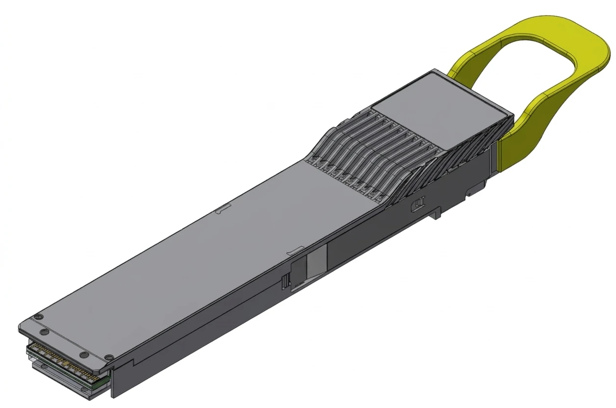
Try a second decode to make the habit stick. A part marked 400G QSFP-DD SR4 reads as: 400 gigabits total, in a QSFP-DD housing, as a short-reach design, over four parallel lanes, each carrying 100G on multimode fiber. Same reading method, different product, and now you know it pairs with multimode patch cords and short runs before you even open a datasheet.
The reach letter is its own language, and it tells you which fiber and how far:
|
Code
|
Stands for
|
Fiber type
|
Usual reach
|
Typical job
|
|
SR / VR
|
Short / very short reach
|
Multimode
|
Tens of meters to about 100 m
|
Rack and row links
|
|
DR
|
Data-center reach
|
Single mode, parallel lanes
|
About 500 m
|
In-building AI and leaf-spine links
|
|
FR
|
Far reach
|
Single mode, WDM
|
About 2 km
|
Cross-building links
|
|
LR
|
Long reach
|
Single mode
|
About 10 km
|
Campus and metro edge links
|
|
ER / ZR
|
Extended / ultra reach
|
Single mode, sometimes coherent
|
40 km to 80 km and beyond
|
Data-center interconnect
|
Pro Optix's standards guide walks through this same naming system from the buyer's side. One design choice hides inside it: DR-class links spend extra fibers to keep the optics simple, while FR-class links use wavelength multiplexing (several colors of light sharing one fiber) to save fiber at the cost of more complex optics. Neither is better; the right pick depends on your distance, your spare fiber count, and your budget. If you are choosing jumpers to match, our fiber patch cords page lists the pairings.
7. Does 800G Make Light Travel Faster?
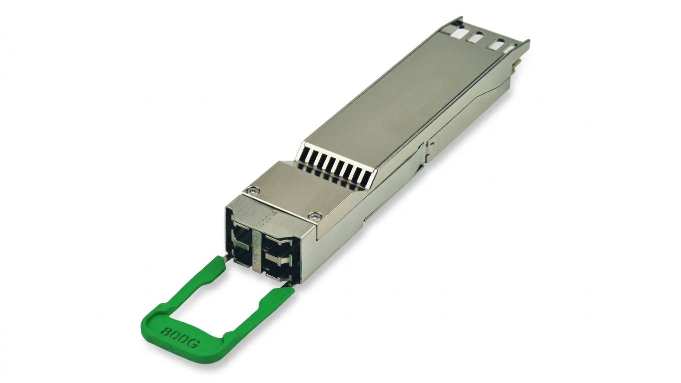
No. Light still moves through glass at roughly 200,000 kilometers per second no matter what module you plug in. Higher speeds come from packing more data into each second: faster symbol rates, denser modulation like PAM4, and more parallel lanes, not from speeding up the light itself.
This misconception matters more than it seems, because it distorts buying decisions. A 1.6T module does not deliver data "twice as fast" in time terms; latency per hop stays essentially unchanged. What it delivers is more data in the same time window.
So when you compare a 100G link to an 800G link, the photons move at the same speed in both. The 800G link simply carries eight times more of them per second, split across eight lanes. Distance math stays the same too: a 500 m class module works to 500 m whether it carries 10G or 800G inside.
There is one nuance worth knowing. Faster signals suffer more from dispersion, the way a light pulse spreads out as it travels, which is why reach classes exist at every speed tier. The light does not slow down or speed up; the data just gets harder to read cleanly as distance grows, and the DSP and laser quality decide how far a link can stretch before the eye diagram closes.
One related warning while we are busting myths: a lit link LED does not prove a correct link. A port can glow green while running errors behind the scenes. The module itself knows the truth, and the next section shows how to ask it.
8. How Does the Module Tell You Something Is Wrong?
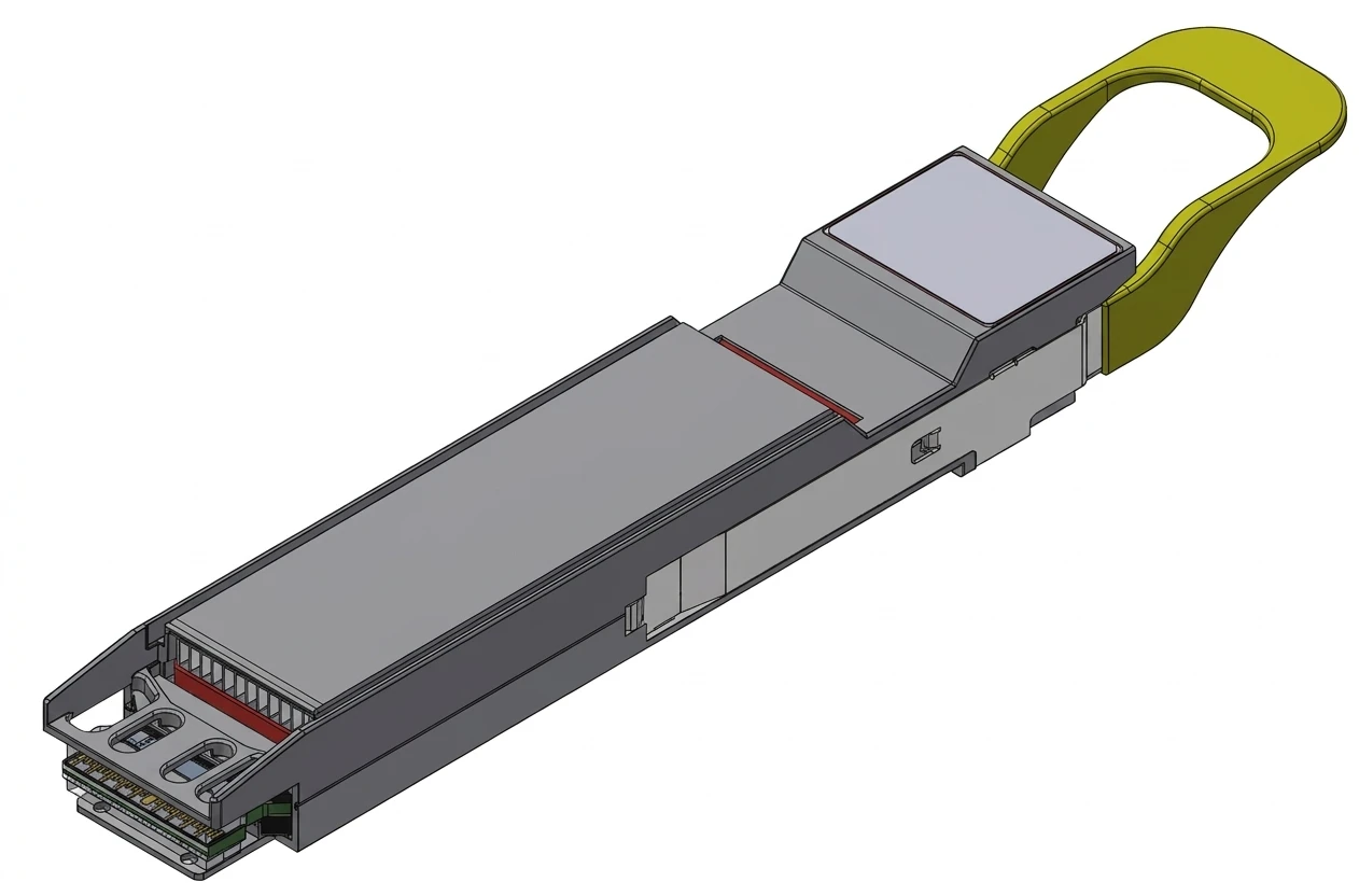
Modern transceivers measure their own health and report five live values over a digital interface: internal temperature, supply voltage, laser bias current, transmit power, and receive power. Each value has warning and alarm thresholds, so your switch can flag a failing module before traffic stops.
The feature is usually called DDM (digital diagnostics monitoring) or DOM (digital optical monitoring), and it is defined in the SFF-8472 management specification published by SNIA. Since this standard, every compliant module carries a small memory and sensor bank readable by your switch. Optcore's DDM guide shows how to pull these values from common switch brands in a few commands.
Reading the values is simple on most switches. Look for a command like "show interface transceiver details", or the optics tab in your management software, and you will see the five readings with their current values, warning levels, and alarm levels side by side. The table below is how our engineers interpret what appears on that screen.
Reading the numbers is where the value is. Here is the cheat sheet our own engineers use:
|
DDM reading
|
What it usually means
|
What to do
|
|
Bias current creeping up month over month
|
The laser is aging and working harder
|
Plan a replacement before it hits the alarm threshold
|
|
TX power below its spec range
|
Laser or driver problem
|
Swap the module and retest
|
|
RX power low on a link that used to be fine
|
Dirty or damaged end face, a tight bend, or added loss somewhere
|
Clean and inspect connectors first, then check the loss budget
|
|
RX power too high on a short link
|
Receiver overload, too much light
|
Use a shorter-reach class or add attenuation
|
|
Temperature high
|
Blocked airflow or a hot neighboring port
|
Check fan paths and port spacing
|
|
Voltage out of range
|
Host board power issue, not the module
|
Investigate the switch, not the optics
|
Two of these rows save the most money in the field. First, bias current trend: a laser near end of life shows a slow, steady climb for months, which turns surprise failures into planned maintenance. Second, RX power: before you swap any module, clean both connector end faces and re-read the value. In our experience a large share of "bad module" tickets end at a dirty ferrule. When the fix is not the end face, the next step is calculating fiber optic loss to see if the link simply exceeds its budget.
Newer high-speed modules extend this idea with CMIS, a richer management interface that also reports per-lane values and error counts. The habit stays the same: the module is its own test bench, so ask it before you touch anything.
9. Why Won't the Link Come Up Even Though It Plugs In?
Physical fit does not guarantee a working link. A link can still fail when the two ends disagree on speed, FEC mode, wavelength, fiber polarity, or power class, or when the switch firmware does not recognize the module's ID code. Check those five agreements before you blame the hardware.
"Plugs in" only covers the mechanical half. Here is the checklist, in the order we run it:
Does the switch support this exact module class? A QSFP-DD port does not automatically accept every QSFP-DD module; the switch lists supported speeds and classes. An OSFP module will not fit a QSFP-DD port at all, no matter how similar they look.
Does the ID code pass the whitelist? Modules carry an ID memory (an EEPROM) that the switch reads on insertion. Many switch vendors only light the port for codes they recognize. A perfectly good third-party module can be blocked by firmware, not by physics.
Do both ends agree on FEC? High-speed links use forward error correction, and the two transceivers must run the same FEC scheme. Mismatched FEC is a silent killer: the link may train but never pass clean traffic. Datasheets name schemes like RS-FEC, and the point is not the acronym but the agreement between the two ends.
Is the fiber polarity right? With MPO parallel links, the fiber array inside the connector must map transmit to receive correctly. Polarity methods (A, B, and C) exist precisely because this goes wrong so often. Our MPO polarity explained guide walks through the methods pin by pin.
Can the port supply the power and cooling? An 800G module draws around 16 watts, several times an older 10G part. Ports are rated for power classes and airflow directions, and a module running hot will throttle or fail.
A classic version of the wavelength trap is worth knowing too. Pair a transmit side running at 1270 nm with a receive side expecting 1330 nm, and every indicator can look normal while no data passes. The meters read fine, the fiber is fine, and the link still goes nowhere, because wavelength agreement is part of the handshake just like speed and FEC.
Run the list top to bottom before swapping parts. In our support experience, polarity and whitelist issues together cause more "dead module" reports than actual dead modules do.
10. What Do AI Data Centers Change About Transceiver Design?
AI clusters connect thousands of GPUs, so they need far more links per device than classic data centers. That demand pushes speeds to 800G and 1.6T, and the hard problems shift from making light to cutting energy per bit, managing heat, and keeping mass production consistent.
During training, GPUs constantly exchange parameters and gradient updates with each other, and the whole cluster waits for the slowest link. So AI builders connect thousands of accelerators with fiber at speeds classic enterprise networks never touched. The market numbers show it: LightCounting's March 2026 Ethernet optics report raised its 2026 growth forecast for Ethernet optical transceivers to 73%, with 800G and 1.6T modules expected to make up roughly 64% of optical module revenue in 2026.
That scale changes the engineering target. When one 800G module draws around 16 watts (AscentOptics' CPO analysis puts a typical pluggable there) and a cluster runs tens of thousands of them, the optics alone consume hundreds of kilowatts. So the industry's race is no longer "who can make light" but "who can move each bit with the least energy".
The standards side is moving too, though not evenly. The IEEE 800G Ethernet standard (802.3df) was approved and published in February 2024. Its successor, the IEEE P802.3dj project, adds 1.6T and 200G-per-lane operation and is still working through draft revisions, with products already appearing ahead of final publication. Buyers should treat "product exists" and "standard final" as two separate checkpoints.
The next step is already visible. Today's 1.6T pluggables mostly split the work across eight 200G lanes in OSFP or QSFP-DD1600 housings, and DSP makers are pushing toward 400G per lane, which would fold 1.6T into just four lanes and cut fiber counts again. Every one of those steps raises the heat and precision stakes for everyone in the chain, chip makers included, and that is exactly where the four routes below compete.
Four technical routes are competing to answer the power question:
|
Route
|
The idea
|
The trade-off
|
|
Discrete EML/DML optics
|
Tune each laser and detector separately for best performance
|
Many parts to align and assemble, cost and power pressure as lanes grow
|
|
Silicon photonics
|
Put modulators, splitters, and multiplexers on one silicon chip
|
Needs an external light source and very tight packaging
|
|
LPO / LRO
|
Remove or slim the module's DSP to save power
|
Tighter link budget, needs controlled short-reach setups
|
|
CPO / NPO
|
Move the optics next to the switch chip itself
|
Harder to service and upgrade, new ecosystem to mature
|
The numbers behind those trade-offs are stark. Cisco's optics team estimates a 400G module at around 12 watts (Cisco Live 2025 presentation), while NADDOD's analysis of CPO architectures reports that co-packaged designs can cut system-level power by more than half versus 15-20 pJ/bit baselines, and AscentOptics compares an 800G pluggable at about 16 watts with an equivalent CPO solution near 5 watts. Even so, pluggable modules keep a decisive advantage for most operators: when one fails, you slide in a replacement in minutes. That is why we expect pluggables and CPO to coexist for years, split by distance and service model. Our 800G optical transceiver guide tracks the pluggable side, and where copper still wins inside a rack, our DAC and AOC cables page covers the shorter-reach options.
11. How Should You Choose a Fiber Optic Transceiver? Seven Questions to Ask
Match the module to your equipment and cabling before comparing prices: confirm the switch port and supported speeds, measure the real link loss, count your spare fibers, plan any breakouts, check cooling, verify interoperability, and make sure you can read its diagnostics. Seven answers, then a shortlist.
Work through the questions in order; each one narrows the field:
|
#
|
Question
|
What to check
|
Common trap
|
|
1
|
Does the port support it?
|
Housing, speed list, firmware version on the switch datasheet
|
Assuming every 800G port accepts every 800G module
|
|
2
|
How far is the real link?
|
Worst-case loss including connectors and splices, not label distance
|
Buying a 10 km module for a marginal 300 m link with dirty ends
|
|
3
|
How many fibers are free?
|
MPO parallel links use 8 or 16 cores per direction pair
|
Planning duplex habits into an MPO port
|
|
4
|
Do you need breakouts?
|
Whether 2x400G or 4x100G splits are required, and the matching polarity
|
Forgetting that breakout changes the cable, not just the module
|
|
5
|
Can the port cool it?
|
Module power class, heat sink style, airflow direction
|
Mixing high-power modules into ports budgeted for older classes
|
|
6
|
Will the two ends agree?
|
ID coding, FEC mode, wavelength plan, end-face finish
|
Buying modules that pass the plug test but fail the whitelist
|
|
7
|
Can you monitor it?
|
DDM or CMIS support and switch-side tooling
|
Blind modules that hide an aging laser until it dies
|
Question 2 is where budgets are won or lost. A module class chosen by label distance ("it's only 2 km, so LR is fine") ignores connector loss, splices, and aging. The pros check the numbers first, and our transceiver types from 1G to 800G guide pairs each speed class with its realistic reach. Question 6 is where partnerships matter: a supplier that codes modules correctly and stands behind interoperability saves you from the whitelist wall. And when the link is short enough that transceivers become optional, compare them honestly with our DAC vs AOC vs AEC vs ACC breakdown.
Question 7 closes the loop with the diagnostics section above. If you cannot read a module's DDM or CMIS data on your own switch, you lose the early warning system that turns surprise outages into planned swaps, so treat monitoring support as a purchase requirement, not a nice-to-have.
12. The Factory View: Why Manufacturing Consistency Is the Real Bottleneck
Two modules can carry the same datasheet and still behave differently in your network. The difference is made, or lost, on the production line, in steps the datasheet never mentions: chip screening, optical alignment, burn-in, and end-face cleanliness. That is where a module's real margin comes from.
Here is what actually happens inside a serious production flow, and why each step exists:
Chip screening. Every DFB and EML chip is tested before it enters a module. Chips from the same wafer vary in threshold current and efficiency, and only screened chips get matched to the right driver settings.
Active alignment. A robot positions the lens over the laser while measuring the light that actually couples into the fiber, then locks everything in place at the optimum. Alignment errors of a few micrometers can cost decibels of power, and decibels are reach.
Burn-in. Finished modules run at elevated temperature for hours so that "infant mortality" failures happen at the factory, not in your switch.
DDM calibration. The diagnostic values from the earlier section are only useful if they are calibrated. Uncalibrated DDM is a random number generator with a nice interface.
End-face control. A single dust speck on a ferrule can add loss that reads as a "bad module". Cleanliness checks sit at the end of our line for the same reason they should sit at the start of your installation.
We emphasize this because COBTEL's position is unusual: we make the DFB and EML chips, the finished optical modules, and the MPO and fiber cords in our own facilities, with design, mold making, testing, and production under one roof. Twenty-plus years of OEM programs for top-10 cabling brands and Fortune 500 projects such as Schneider have taught us one lesson worth passing on: ask any supplier how they screen, align, and burn in. The answers tell you more than the datasheet does.
When you evaluate any module supplier, five questions separate the serious ones from the rest. Do they test chips before assembly? Do they align optics actively, with measured coupling, or just fix the parts and hope? How long is the burn-in? Are the DDM values calibrated unit by unit? And will they share test data with every shipment? A supplier who answers all five without hesitation is worth a phone call; one who stalls is worth a second sample batch before a first purchase order.
Three things are worth carrying away from this guide. A fiber optic transceiver is a two-way translator with a five-station chain on each side. Part numbers are sentences, so read the speed, housing, reach, and lane count before you buy. And the module watches its own health, so DDM readings are your first troubleshooting step, not your last resort.
If you are planning links for a data center, a campus, or an AI cluster, tell us your switch model, link lengths, and fiber counts through the inquiry form at the bottom of this page. Our engineers reply within 12 hours with a quote, and free samples let you test the real thing before you commit. From DFB and EML chips to finished modules and MPO cords, everything is designed, made, and tested under one roof, and we are happy to put that roof to work for you.
13. Frequently Asked Questions
1. How long does a fiber optic transceiver last?
Most quality modules run reliably for many years, and laser lifetime is the limiting factor, not the electronics. The laser's bias current climbs slowly as it ages, which is exactly what DDM tracking reveals. A module whose bias current trends up for months is telling you to schedule a replacement, ideally before it reaches the alarm threshold.
2. Can I use a third-party transceiver in my switch?
Often yes, but check three things first. The module must follow the same MSA standard as the port, its ID code must pass your switch vendor's firmware whitelist (or be coding-service compatible), and the supplier should offer interoperability support. Physics rarely blocks third-party modules; firmware policies are the usual gatekeeper.
3. What is the difference between a transceiver and a DAC or AOC cable?
A transceiver is a module you plug into both ends of a fiber link. A DAC (direct attach cable) has fixed electronics built into the cable ends, and an AOC (active optical cable) has fixed optical modules built in, so neither has a replaceable module. DACs win on cost and power inside a rack, transceivers with patch cords win on flexibility and distance.
4. Why is my transceiver's RX power low?
Start at the connector end faces, because contamination is the most common cause; clean both ends and re-read the value. Next check for tight bends or pinched cable runs, then verify the link length against the module's loss budget. If the fiber plant checks out and RX power is still low, only then suspect the module's photodiode or the far-end laser.
5. What do SR, DR, FR, and LR mean on a transceiver?
They are reach classes that tell you the fiber type and intended distance: SR for short multimode links up to about 100 m, DR for single-mode parallel links around 500 m, FR for single-mode wavelength-multiplexed links around 2 km, and LR for single-mode links around 10 km. The letters follow a consistent system across the industry, so once you can read them, most datasheets become predictable.