800G Optical Transceiver
Mar 19, 2025
Leave a message
Today, we have something very interesting: a closer look at the COBTEL COLORZ 800(OSFP112-DR8 Precision Optical Fiber Transceiver). This is a long-distance ZR+ 800G optical transceiver, using the standard OSFP pluggable form factor, but it can achieve speeds of 800Gbps over distances of 500 kilometers or even more than 1000 kilometers. It can even be configured to support 400Gbps communication over distances of up to 2500 kilometers. We got an inside look at the COBTEL lab to understand how this coherent optical technology works and wanted to show you how they achieve this.

1.The COBTEL COLORZ 800 can achieve 800Gbps speeds over 1000 kilometers.
Nowadays, the rule in data centers is basically: use copper cables as much as possible, and when the distance is too far, use fiber optics. If you look at products like the NVIDIA GB200 NVL72, you'll find that its biggest innovation is the ability to use copper cables on the backend to interconnect 72 GPUs and switches.

Beyond a cable length of about 3 meters, high-speed lines and copper cables cannot be used together due to signal integrity issues.

While copper cables can usually reach within and adjacent racks, optical transceivers can be used to span longer distances. However, there's a catch. Optical transceivers use different technologies to span different distances at different speeds.

Short-range optical transceivers operating at 10Gbps or 100Gbps are much cheaper to manufacture than long-range optical transceivers operating at 400Gbps or 800Gbps, largely because the complexity of the technology is increasing.

Another aspect is the form factor (the physical size and shape of the module) of the optical transceiver.
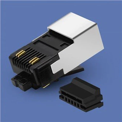
CFP-style form factor modules are more common in telecommunications applications. In data centers, we tend to see small SFP modules for low-end applications and larger QSFP and OSFP modules for high-speed applications. Even common AI infrastructure NICs, like the NVIDIA ConnectX-7 400GbE adapter, use OSFP. Today we are discussing the COBTEL COLORZ III 800G ZR+ OSFP module. OSFP provides a larger module standard with power, cooling, and more importantly, the space needed to handle all the components. It looks like this:

Simply put, on one side, the module receives electrical signals from the device.

On the other end, we have the optical transmit and receive ports where the fiber optic cables are inserted.

While this sounds simple, something remarkable happens inside the metal casing. Electrical signals are converted into optical signals, and optical signals are converted back into electrical signals. We'll explain what happens inside at a high level so that most people can understand.
Next, we'll take a look inside the OSFP casing and explain how it works.
2. The COBTEL Optical Lab is internally equipped with the COLORZ 800 ZR+ optical transceiver.
It has been demonstrated that the placement of components within the optical transceiver is critical. Even a one-millimeter deviation in component placement can significantly impact its performance. Typically, companies discourage disassembling these high-end modules. Instead, we observed a demonstration in COBTEL's lab, which was essentially a blown-up version of what's inside that small metal OSFP enclosure.

Of course, a large circuit board laid out like this is not suitable for networking devices, so another impressive aspect is not just the ability to create 400Gbps 2500km or 800Gbps 1000km communication modules, but also to package them into standard pluggable form factor modules.
Looking at this platform, the first thing you'll notice is the short DAC (Direct Attach Cable). This is the 800Gbps electrical signal interface.
. This is the 800Gbps electrical signal interface.")
This is a view of the development board from the other side.

You can think of this as the electrical side of the module you see here:

The first stop is through the COBTEL Orion DSP. This is the component between the electrical and optical ends, used to clean up the signal.

To give you a sense of what's inside, here's the COBTEL Orion DSP and the COLORZ III 800G ZR+ module it's housed in. This OSFP module sits above the older generation COLORZ II (400G) and COLORZ I (100G) pluggable modules.
 and COLORZ I (100G) pluggable modules.")
These DSPs are impressive because they must handle significant processing tasks within a highly constrained space and power budget. While ordinary 10Gbps or 25Gbps NIC chips are made using significantly older process technologies, these DSPs are manufactured using a 5nm process to handle the power and space constraints within the OSFP module footprint.
Starting from the DSP, the transmission signal is routed to the CDM, or Coherent Driver Module, which is the smaller of the two golden/brass boxes below, where a single fiber is connected.

For the sake of brevity, we won't go into the details of how the PIC operates, but in that small box, we have the components needed to convert electrical signals into optical signals using a laser source, modulators, and other components. At one end of the box, we input electrical signals, and at the other end, we output light onto the fiber bundle. This is the transmission end on this demo board.
At this point, you might have guessed that the slightly larger box on the left is the receiving end, known as the ICR, or Integrated Coherent Receiver. If you often use single-mode LC cables and optics, you'll immediately notice: there are two fiber cables on the receiving end. This is where this technology is slightly more complex than low-cost and low-speed optics that only perform direct detection ("is there light or not" type of analysis).

Not only is there a receiving end fiber on the circuit board, but there is also a local oscillator that feeds a second signal into the ICR. Think of it as a reference signal for phase comparison. Inside the ICR is a 90-degree hybrid, a passive component that helps maintain phase and amplitude information, among other things. The ICR is also equipped with photodetectors to receive optical signals and then produce electrical outputs at the other end. The electrical signals are typically weak, so we use a TIA, or transimpedance amplifier, to convert the weak current from the photodetector into a measurable voltage. Think of it as an amplifier on the electrical side.

Typically, these components also require cooling, so the reference board looks more like this:

Even the reference laser source requires a heat sink for cooling. When I mention that we managed to get into the lab, it's clear that this is a true lab setting.

Then, the electrical signals from the ICR can be fed into the Orion DSP on the electrical side.

This completes the full cycle of signal processing, covering both the electrical and optical domains.

It's important to note that each side of this development platform is ultimately packaged and thermally managed within the OSFP form factor.

Beyond the hardware, let's briefly discuss the necessity of a reference laser signal and the distinction between direct detection and coherent detection.
3. Direct Detection and Coherent Detection
As part of the article, one of my ideas is to explore the differences between direct detection and coherent detection, which are commonly used in low-end, low-cost optical devices.
Those who need to delve deeper into mathematics and physics may already be familiar with this. Many signal detection methods focus on the simple question of whether a signal is present or not. In a very basic 10Gbps module, this can be framed as "Is there light or not?" This can be represented in many fairly simple 2D ways, as well as through more complex encoding schemes. In the lab, we often see eye diagrams-graphical representations of signal quality-like the one shown below (from Intel's 2019 Silicon Photonics division, which Intel sold that same year).

Coherent detection is much more complex, as it allows for more advanced techniques using light. Instead of just detecting the presence of light, we can observe the "constellation" of the signal. Both diagrams display X and Y polarization, resulting in 16 possible constellations.

This is why having a local oscillator reference is crucial. For more complex encodings, we need the additional information provided by that reference.
If you're curious about the differences between direct detection and coherent detection, there are plenty of detailed papers on the topic. For STH viewers, the key takeaway is that while the 800G ZR+ OSFP module may look like a slightly larger 100G SR4 QSFP28 module, its internals are vastly different.
So, the big question is: "Why does any of this matter?" A simple reason is that deploying data centers across regions can be advantageous for cost and resilience. Directly connecting from a switch to a data center 1000 kilometers or more away enables organizations to host more infrastructure at lower-cost, stable locations. Additionally, if you have two geographically distant campuses, linking them with 400Gbps to 800Gbps bandwidth could be a game-changer.

But in reality, one of the biggest drivers of pluggable optics today is the construction of AI data centers. This construction is constrained by power availability, so data center operators are focusing on securing power. Plans include building large data centers next to existing power plants, creating new power sources for data centers, and more. Minimizing transmission losses helps maximize the power available for computing. The challenge is that clusters require so much power that relying on a single site may no longer be feasible.

We often hear the idea of locating multiple data centers near power sources rather than concentrating computing in one campus. Interestingly, this is also what many cryptocurrency miners were exploring in the mid-to-late 2010s. The difference is that mining farms don't require high-bandwidth, low-latency mutual access, whereas AI clusters do.
The idea is that building large-scale clusters across multiple sites near available power sources can save on power transmission losses and costs, and it may also be simpler. Instead of licensing and building large power sources, organizations can light up dark fiber-unused optical fiber cables-or lay additional fiber to bridge clusters at several smaller power sources.
 to establish fast links spanning long distances in a relatively cheap and easy way.")
So, the simple answer is that these modules allow organizations to use common pluggable optical transceivers (rather than dedicated DCI boxes) to establish fast links spanning long distances in a relatively cheap and easy way. What's even more exciting is the potential for large-scale geographic distribution of AI resources.
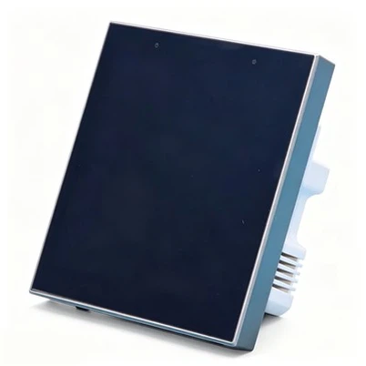
Pluggable modules often appear as simple metal shells. From this perspective, it's hard to tell why one is more complex than the other.

By examining the internals of high-end modules, we can better understand the complexity within these pluggable optics. We looked at a simple, low-cost 100G SR4 optical transceiver, which is very different from the 800G ZR+ optical transceiver. The reason is that although they look similar, the COLORZ III module can transmit data at 8 times the rate over distances 10,000 times greater. That's probably why I thought it was such a cool demo when I first saw it.
4. 100G QSFP28 DAC Internal Structure Quick Teardown
Some may have noticed from the previous context that we also disassembled a 100G QSFP28 DAC and a 100G SR4 QSFP28 optical transceiver. We think it's important to show you what's inside the module, so this article will reveal what's inside the DAC casing.
The cable we are about to open is labeled as an Intel DAC. This is a fairly typical QSFP DAC, with an electrical connector on one end and a cable on the other.

Opening the casing is quite easy. Some casings, like this one, use simple screws to hold them together. Others use more difficult-to-open connection methods. We recommend that if you are opening the casing yourself, try to use one with easily tightened screws. Also, be aware that the QSFP28 fixing mechanism usually has a spring. It's well known that when opening these casings, the spring can pop out of the casing.

Inside the casing, we can see that the PCB is very simple. In fact, you can see many traces between the QSFP28 connector and the internal wires of the cable.

The module has thick shielded wires, the same length as the DAC. Each wire has a number, which might be helpful for manufacturing. The connections and wire ends are coated with resin or epoxy to secure them to the PCB solder points. Then we get some copper tape and a flexible cable exit with curved supports. Both sides look very similar.
 side. The alignment of the optical fibers must be more precise, and the photon-to-circuit interface is much more complex than the internal structure of the DAC.")
Just to give you an idea, here's what the inside of a low-cost QSFP28 100G SR4 DAC looks like, specifically the PIC (Photonic Integrated Circuit) side. The alignment of the optical fibers must be more precise, and the photon-to-circuit interface is much more complex than the internal structure of the DAC.
Most folks will never need to peek inside a DAC. They are designed to be plug-and-play, requiring no maintenance. Still, we think it's worth opening one end of the casing to show how these cables work. We should at least point out that these are passive cables. There are AECs (Active Electrical Cables), which have active retiming chips in the cable connectors that help improve signal quality, allowing high-speed signals to travel further over copper. AECs are more complex, power-hungry, and costly. That said, when it comes to the simplicity of DAC design, we hope these photos give you a better idea.