QSFP-DD vs OSFP: The Complete 400G Optical Transceiver Selection Guide
Jun 22, 2026
Leave a message
TL;DR: QSFP-DD and OSFP are the two leading 400G transceiver form factors, but they solve different problems. QSFP-DD offers backward compatibility with QSFP28 and higher port density, making it the best upgrade path. OSFP delivers more thermal headroom for high-power coherent optics and AI clusters. This guide covers specs, migration paths, total cost of ownership, deployment steps, and troubleshooting so you can choose with confidence.
Choosing between QSFP-DD, QSFP28, and OSFP might seem like a small technical detail. It's not. This decision shapes your entire network architecture, your future upgrade path, and your long-term spending. Pick the wrong QSFP-DD vs OSFP form factor, and you could face expensive rip-and-replace cycles or stranded assets worth hundreds of thousands of dollars.
As data centers race toward 400G, 800G, and beyond, the form factor question keeps coming up. Should you stick with the familiar QSFP ecosystem? Go all-in on OSFP for maximum performance? Or take the middle path with QSFP-DD's backward compatibility?
At COBTEL 1, we've spent over 20 years manufacturing optical transceivers, MPO patch cords 2, and high-speed optical chips. We've helped Fortune 500 companies navigate exactly this decision. This guide gives you everything you need: spec comparisons, migration strategies, real cost numbers, step-by-step deployment instructions, and troubleshooting frameworks.

Quick Reference: QSFP-DD vs QSFP28 vs OSFP at a Glance
Before diving deep, here's the side-by-side comparison that matters most:
QSFP28 is today's workhorse. QSFP-DD is the upgrade path that protects your existing investment. OSFP is the high-performance option built for greenfield deployments. Choose wrong, and you'll either overspend or paint yourself into a corner.
What Is QSFP28 and Where Does It Stand Today?
QSFP28 (Quad Small Form-factor Pluggable 28) is the standard 100G transceiver form factor. It uses four 25G NRZ electrical lanes to deliver 100Gbps total bandwidth in an 18.35mm-wide package with up to 6W power consumption. Since 2016, it has been the backbone of enterprise and cloud data center networks.
Core features:
4× 25G NRZ electrical lanes
18.35 mm width (same as QSFP+ and QSFP-DD)
Maximum power draw of approximately 6W
Mature ecosystem with broad vendor support
QSFP28 dominates current enterprise and cloud data centers. If you're running a 100G network today, you're almost certainly using QSFP28 modules. The question isn't whether to replace them. It's when and how to upgrade.
The QSFP28 form factor 3 maxes out at 100G with no upgrade path. You can add more ports, but you can't push more speed through a single module. That ceiling is what drives the move to QSFP-DD or OSFP.
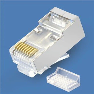
What Is QSFP-DD and Why Is It the Go-To Upgrade Path?
QSFP-DD (Double Density) doubles the electrical lanes to eight while keeping the exact same 18.35mm width as QSFP28. It supports 400G (8×50G) and 800G (8×100G) speeds, and it is backward compatible with QSFP28 modules. You can deploy QSFP-DD switches today, keep using your existing 100G optics, and upgrade to 400G by swapping modules when you're ready.
The "Double Density" name refers to the electrical interface, not physical size. QSFP-DD achieves this by adding a second row of electrical pins in a slightly deeper connector. From the outside, a QSFP-DD module 2 looks almost identical to a QSFP28.
Core features:
8× 50G/100G PAM4 electrical lanes
Same 18.35 mm width as QSFP28
Supports 400G (8×50G) and 800G (8×100G)
Backward compatible with QSFP28 modules
The backward compatibility advantage is enormous. You can deploy QSFP-DD switches now, run your existing QSFP28 100G modules in those ports, and upgrade individual links to 400G as bandwidth demands grow. No stranded assets. No forklift upgrade. The QSFP-DD MSA 4 designed this compatibility from the start.
What Is OSFP and When Should You Choose It?
OSFP (Octal Small Form-factor Pluggable) is a purpose-built high-performance form factor. It's 22.58mm wide (23% wider than QSFP-DD), with integrated heatsink support and up to 25W power capacity. OSFP is designed for AI training clusters, long-haul coherent optics, and future 1.6T modules. It does not support any QSFP-family modules.
OSFP took a different design approach. Instead of maintaining backward compatibility, the OSFP MSA 5 prioritized thermal headroom and future-proofing.
Core features:
8× 50G/100G PAM4 electrical lanes
22.58 mm width (23% wider than QSFP-DD)
Up to 25W maximum power
Zero compatibility with QSFP-family modules
OSFP shines where thermal headroom matters most. AI training clusters running high-power GPU interconnects, long-distance coherent ZR+ optical systems, and future 800G OSFP modules/1.6T modules all benefit from the extra space and cooling capacity. If you're building new infrastructure with no legacy QSFP28 equipment, OSFP deserves serious consideration.
How Does Backward Compatibility Actually Work?
Backward compatibility is one-way, not two-way. A QSFP-DD port accepts QSFP28 modules, but a QSFP28 port cannot accept QSFP-DD modules. No adapter can reverse this. OSFP is completely isolated from the QSFP family, with different pin counts, widths, and latch mechanisms.
This is the most confusing part of the QSFP-DD vs OSFP comparison. Let's clear it up.

Compatibility Matrix
Why One-Way Compatibility Works
QSFP-DD ports accept QSFP28 modules because the physical dimensions align. The QSFP-DD slot is deeper to accommodate extra electrical pins. A QSFP28 module simply sits shallower in the slot, and the electrical signals are compatible.
The reverse doesn't work for two reasons:
Physical mismatch: QSFP-DD modules are deeper than QSFP28 slots. They won't fit.
Electrical mismatch: QSFP-DD needs 8 lanes. QSFP28 provides only 4. Even if you could force it in, it wouldn't work.
OSFP: Completely Isolated
OSFP uses a 60-pin connector with a different pinout, a 22.58mm width that won't fit QSFP slots, and a different latch design. It's electrically and mechanically isolated from the QSFP family.
QSFP28-to-OSFP adapter modules do exist, but they add cost, complexity, and failure points. They work for a handful of legacy connections. They're not a migration strategy.
Physical and Performance Comparison
Form Factor Dimensions
The width difference between QSFP-DD and OSFP directly impacts port density. A 1RU switch fits 36 QSFP-DD ports but only 32 OSFP ports. Deploy 100 switches, and OSFP gives you 400 fewer ports, or you need 12 extra switches to match capacity.
Power and Thermal Differences
Power consumption scales with speed and complexity:
QSFP-DD handles standard 400G modules without issues. But high-power ZR coherent modules push it close to its thermal ceiling. OSFP's integrated heatsink and larger volume provide comfortable headroom for modules above 20W.

Speed Roadmap
QSFP28: Maxes out at 100G. No upgrade path beyond adding ports.
QSFP-DD: Currently supports 400G. With QSFP-DD800, it reaches 800G using 100G-per-lane electrical signaling. 1.6T is theoretically possible but thermally challenging.
OSFP: Supports 400G and 800G today. It's the preferred form factor for 1.6T modules 2 on the Ethernet Alliance industry roadmap.
How Do You Migrate from QSFP28 to 400G?
For most organizations, the recommended path is QSFP28 to QSFP-DD. Deploy QSFP-DD switches, keep your QSFP28 modules running, and upgrade backbone links to 400G first. A typical migration takes 12 to 24 months and can save over $340,000 compared to a full equipment replacement.
Path 1: QSFP28 → QSFP-DD (Recommended for Most)
When to use: You have existing QSFP28 modules worth preserving.
Steps:
Deploy QSFP-DD switches while continuing to use QSFP28 modules
Upgrade high-bandwidth backbone links to 400G QSFP-DD first
Gradually upgrade Top-of-Rack (ToR) connections as servers get new NICs
Timeline: 12-24 months for full migration
Cost advantage: You preserve existing optics assets, pay zero adapter costs, and spread capital expenditure over budget cycles.
Real-world example: A financial services operations team held 340,000 saved.
Path 2: QSFP28 → OSFP (Rarely Used)
When to use: You need high-power ZR+ modules and have minimal existing optics inventory.
Steps:
Replace all optical modules
Deploy QSFP28-to-OSFP adapters for legacy connections (400 each)
All new capacity uses OSFP
Timeline: Immediate cutover; no phased migration possible
Cost reality: Full module replacement plus 400 per legacy connection for adapters.
QSFP-DD vs OSFP: New Build Selection Guide
Choose QSFP-DD When:
Building enterprise or cloud data centers
Running mixed workloads
Planning future integration with existing infrastructure
Per-module power stays below 15W
Choose OSFP When:
Building AI training clusters
Long-distance DCI requiring ZR+ coherent modules
No legacy compatibility requirements
Need maximum thermal headroom for future modules
Selection Flowchart
Step 1: Do you have existing QSFP28 infrastructure?
Yes → Choose QSFP-DD (backward compatibility value is too high to ignore). Done.
No → Go to Step 2.
Step 2: Do you need ZR+ coherent optics or 1.6T in the near future?
Yes → Choose OSFP (thermal headroom is essential). Done.
No → Choose QSFP-DD (broader ecosystem, higher port density). Done.
What Does Total Cost of Ownership Really Look Like?
In a 100-rack data center migrating 2,000 ports from 100G to 400G, QSFP-DD saves approximately $660,000 over three years compared to OSFP. The savings come from reusing 60% of existing QSFP28 optics, needing 12% fewer switches due to higher port density, and eliminating adapter costs.
Module Pricing
Module prices are comparable across form factors:
Price isn't driven by form factor. It's driven by volume, vendor, and specifications.
Infrastructure Cost Factors
Switch costs: QSFP-DD switches cost 400 less per port than OSFP, thanks to higher shipment volumes and simpler thermal designs.
Power and cooling: OSFP modules draw slightly more power on average. Over three years, that adds 100 per switch in electricity costs.
Migration costs: QSFP-DD's backward compatibility means zero adapter spending. OSFP requires adapters (400 per port) or full module replacement.
TCO Case Study: 100-Rack Data Center
Scenario: 2,000 ports migrating from 100G to 400G.
QSFP-DD approach:
Reuse 60% of QSFP28 optics, saving $480,000
Zero adapter costs
Higher port density means 12% fewer switches, saving $180,000
Three-year TCO advantage: ~$660,000
OSFP approach:
Full module replacement: $1,200,000
Legacy connection adapters: $160,000
More switches needed for equal capacity: +$180,000
Three-year TCO premium: ~$1,540,000
For greenfield builds with no existing modules, the gap narrows. But QSFP-DD still wins on switch cost and port density.
Real-World 400G Deployment Scenarios
Scenario 1: Enterprise Data Center Refresh
Situation: Mid-size enterprise with 5-year-old 100G infrastructure and 200 QSFP28 modules in service.
Need: Upgrade backbone to 400G while keeping ToR at 100G during transition.
Decision: QSFP-DD.
Result: 18-month smooth migration with zero business disruption. Legacy modules retired naturally as servers were upgraded. Saved $300,000 compared to full equipment replacement. Budget spread across quarterly cycles.
Scenario 2: New AI Training Cluster
Situation: AI startup building its first GPU cluster. No existing infrastructure.
Need: 400G direct-connect per GPU. Cross-campus model sync requires ZR+ coherent optics.
Decision: OSFP.
Why: No legacy compatibility needed. ZR+ modules at 22W require OSFP's thermal headroom. Future 800G/1.6T roadmap aligns with OSFP.
Result: Deployed 64-port OSFP switches. ZR+ modules ran within thermal spec at 22W. Clear upgrade path to 800G and beyond.
Scenario 3: Hyperscaler Multi-Region Deployment
Situation: Large cloud provider expanding to new regions. Existing facilities use QSFP28/QSFP-DD.
Need: Standardize new builds while maintaining existing sites.
Decision: OSFP for new regions only.
Why: New builds have no legacy constraints. New capacity standardized on OSFP. Existing facilities stay on QSFP-DD.
Result: Dual-standard management through standardized procurement. New regions use OSFP, existing facilities keep QSFP-DD. Supply chain simplified for new capacity.
400G OSFP Step-by-Step Deployment Tutorial

Getting 400G OSFP right requires attention to details that datasheets don't always highlight. Here's the complete process from planning to production.
Pre-Deployment Planning
Power Budget Reality Check
Vendor datasheets list 400G OSFP module power at 12-15W. Real-world production power runs higher. In production testing, single modules draw about 15-20W. Coherent ZR/ZR+ modules reach 18-23W.
For a fully loaded 32-port 400G OSFP switch:
Conservative estimate: 32 ports × 15W × 2 (both ends) = 960W for optics alone
Realistic estimate: 32 ports × 18W × 2 = 1,152W
Add switch ASIC power (~300-400W for 400G switches)
Total per switch: 1,300-1,550W
Check your cabinet power distribution and cooling capacity before purchasing hardware. We've seen data center teams skip thermal calculations and then face throttling issues post-deployment, ultimately needing airflow baffles and wider cabinet spacing to stabilize.
Heatsink Verification: Flat-Top vs Finned-Top

This is the detail that has delayed multiple real-world projects. 400G OSFP modules come in two physical heatsink variants:
When connecting switches to server NICs directly, each end may need a different heatsink type. Confirm and order correctly before installation. Field modifications void warranties and risk equipment damage.
Fiber Infrastructure Assessment
Confirm your existing fiber supports 400G:
SR8 requires OM4 or OM5 multimode fiber (OM3 is not supported)
DR4/FR4/LR4 requires OS2 single-mode fiber
Fiber deployed before 2015 may not meet 400G signal integrity requirements
MPO connectors must be APC polished (8° angle); UPC will not work
If you have any doubts about fiber quality, test before buying modules. 400G is far less forgiving of fiber imperfections than 100G.
400G OSFP Module Types and Specifications
SR8 and DR4 use parallel optics (8 lanes transmitting simultaneously). FR4, LR4, ZR, and ZR+ multiplex channels onto fewer fibers using CWDM/DWDM.
6-Step Installation Process
Step 1: ESD Protection. 400G OSFP modules are sensitive to electrostatic discharge. Wear a grounded wrist strap connected to the cabinet ground point. Handle modules by the edges only. Never touch the gold fingers or heatsink fins.
Step 2: Verify Heatsink Type. Double-check the heatsink against your platform requirements. The visual difference is obvious: finned-top has vertical cooling fins and sits taller; flat-top has a smooth surface and lower profile. Wrong type? Stop. Do not remove or modify heatsinks.
Step 3: Insert the Module. Align the module with the OSFP slot and push until the latch clicks. Don't force it. If you feel resistance, check orientation. The module should slide in smoothly with moderate pressure.
Step 4: Clean and Inspect Fiber. This step prevents 70% of deployment link failures. Inspect the MPO connector 2 end face with a fiber microscope before cleaning. If clean, connect directly. If dirty, use an MPO-specific cleaning tool (not standard 2.5mm/1.25mm tools). Inspect again after cleaning. Never clean without inspecting first, as debris can scratch the end face. Target insertion loss: less than 0.5dB per connection point.
Step 5: Connect Fiber. For MPO connections (SR8, DR4): confirm polarity (Type B is the standard for parallel optics), verify male/female connector match, push until the connector latch locks, and maintain a minimum 30mm bend radius. For LC duplex connections (FR4, LR4, ZR): connect TX to remote RX and RX to remote TX, and confirm the LC latch is fully engaged.
Step 6: Verify Link. Check link status on the switch:
Arista: show interface eth1/1 status
Cisco: show interface eth1/1
NVIDIA: ibstat or ip link show
The link should come up within 30 seconds. If it doesn't, begin troubleshooting.
MPO Fiber and Polarity Configuration
MPO polarity is the number-one cause of link failures during 400G turn-up. Understanding the three polarity schemes saves hours of debugging.
MPO-16 vs MPO-12:
MPO-16: 16 fibers, used for 400G SR8 (8 TX + 8 RX). Does not support breakout.
MPO-12: 12 fibers, used for 400G DR4 (4 TX + 4 RX, 4 spare fibers). Supports breakout to 4×100G.
Both require APC polish (8° angle). UPC polish causes back-reflection and link instability.
Polarity schemes:
Type B (crossover) polarity is the industry standard for 400G SR8 and DR4. TX fiber 1 connects to RX fiber 12, TX fiber 2 to RX fiber 11, and so on.
Male/Female verification: MPO connectors come in male (with pins) and female (without pins). They must mate male-to-female. Module ports are typically male. Patch cables are typically female-to-female. Trunk cables are typically male-to-female. Verify before connecting. Forcing mismatched connectors damages pins.
Switch Configuration Commands
Text
Key settings: speed 400gfull explicitly sets 400G speed. mtu 9216 enables jumbo frames for data center traffic. fec rs-fec enables the RS-FEC (KP4) required for 400G.
Cisco NX-OS (e.g., Nexus 9000):
Text
NVIDIA (InfiniBand NDR / Ethernet):
InfiniBand mode:
Text
Ethernet mode:
Text
NVIDIA ConnectX-7 defaults to NDR 400Gb/s InfiniBand. It can be switched to 400GbE Ethernet mode. FEC is mostly auto-managed and rarely needs manual configuration.
FEC note: Both ends must run RS-FEC (KP4) for 400G. FEC mismatch causes link flapping or prevents link-up entirely.
Verification and Testing
Initial link verification (within 5 minutes of turn-up): Confirm link state is UP, speed negotiated to 400G, and FEC is enabled at both ends.
DOM (Digital Optical Monitoring): Check TX power (typically -2 to +4 dBm per module spec), RX power (typically -6 to -1 dBm), and temperature (below 70°C alarm threshold).
Pre-FEC BER monitoring (5-10 minutes):
Pass: < 1×10⁻⁶
Marginal: 1×10⁻⁶ to 1×10⁻⁵
Fail: > 1×10⁻⁵
High pre-FEC BER usually points to poor fiber quality, dirty connectors, or signal degradation. These links may work initially but fail under full load.
24-hour burn-in test: Before going to production, run a 24-hour stress test. Generate line-rate traffic (iperf3, TRex, or simulated production traffic). Monitor error counters hourly. Confirm zero link flaps and zero temperature alarms. Check whether FEC correction counts are rising (which indicates link degradation). Record final DOM readings. Burn-in testing catches infant failures and marginal links before they impact production.
Phased Migration Strategy
Not every deployment goes straight to native 400G. A phased approach reduces risk.
Phase 1: Upgrade Spine Layer. Replace spine switches with 400G-capable platforms. Use breakout cables to connect existing 100G leaf switches. Run stable for 30-60 days.
Phase 2: Gradually Upgrade Leaf Layer. Upgrade leaf switches rack by rack. Use breakout cables to maintain connectivity with older servers. Move to the next batch after confirming stability.
Phase 3: Native 400G. Once all equipment supports 400G, remove breakout cables and run end-to-end native 400G. Keep breakout cables as spares.
Breakout cable option: 400G DR4 modules support 4×100G breakout using MPO-12 to 4×LC duplex cables. This lets a 400G spine switch connect to 100G leaf switches during migration. Per-100G connection power drops from approximately 10W to about 5.5W. This approach lets you deploy 400G infrastructure before all endpoints are ready.
QSFP-DD Troubleshooting Guide: Solving 400G/800G Link Issues Fast
About 70% of QSFP-DD faults resolve at the physical layer: dirty connectors, partially seated modules, and cable problems. Before replacing any hardware, follow a structured five-stage process covering physical inspection, CMIS verification, configuration checks, signal quality analysis, and isolation testing. This approach solves roughly 90% of issues.
Here's a real story: an engineer spent two days processing RMA returns for twelve QSFP-DD modules on a Cisco Nexus switch. The system kept showing %SFP4UNSUPPORTED_SENSE. Replacement modules showed the same error. A colleague suggested checking switch firmware. The root cause? New CMIS 4.0 modules were incompatible with the switch's older CMIS 3.0 firmware. Two days of work, completely wasted.
The Five-Stage Troubleshooting Framework
Always work through stages in order. Confirm the physical layer is good before moving to Stage 2. Confirm module identification and configuration before analyzing BER in Stage 4. This structured approach prevents engineers from guessing blindly and wasting hours.

Stage 1: Physical Layer Inspection
A module that seems "broken" often just needs 30 seconds and a lint-free wipe. Effective troubleshooting always starts at the simplest failure point.
One data center technician spent 3 hours troubleshooting a 400G DR4 link that wouldn't come up. Configuration checks, firmware upgrades, port swaps: nothing worked. Finally, they pulled the module and inspected the MPO connector under a fiber microscope. A single tiny fiber from a cotton swab was stuck on the fiber array. Cleaning took 30 seconds. The link came up immediately. The "broken module" was just dirty glass.
Visual inspection checklist:
Module fully seated: Push firmly until you hear the latch click. Incomplete insertion is the top cause of intermittent lane errors.
Gold fingers: Check electrical contacts for corrosion, debris, or bent pins. A single bent pin on lane 3 kills a 400G link.
Connector damage: Look for cracked ferrules, missing boots, and kinked cables. 400G MPO-16 connectors are more fragile than MPO-12.
Dust caps: Modules stored without dust caps are already contaminated.
Good cable hygiene is the foundation of efficient QSFP-DD troubleshooting. Connector contamination alone accounts for the majority of optical module failures in 400G deployments. For a deeper look at cable types and compatibility, check our QSFP-DD cabling guide 2.
MPO connector cleaning process:
Connector contamination causes 65-70% of 400G link failures. In PAM4 modulation, even tiny debris creates enough loss to close the signal eye.
Inspect first: Use a 400× fiber microscope. Check the end face for dust, oil, or debris. Never clean without inspecting first.
Wet-to-dry wipe: Apply one drop of fiber cleaning fluid on a lint-free wipe. Draw the connector across the wet zone, then the dry zone.
Confirm APC polish: 400G QSFP-DD modules use APC (Angled Physical Contact) connectors with an 8° polish angle. If you see a flat blue end face, that's UPC. You must use green APC connectors.
Re-inspect: Clean until the end face passes inspection. One retry takes 30 seconds; a link failure costs hours.

Cable and environment checks:
Bend radius: Single-mode fiber requires a minimum 30mm bend radius. Over-tight cable management causes microbend loss, an easily overlooked variable.
Strain relief: Heavy MPO trunk cables pulling on modules cause intermittent contact issues. Few engineers check this first.
Airflow and thermal shadowing: In belly-to-belly cage configurations, upper-row modules inhale preheated exhaust air from lower-row modules. Upper ports run 10-15°C hotter.
Stage 2: Module Identification and CMIS
Switches don't always report module status accurately. "QSFP-DD not detected" is one of the most common and frustrating field issues.
The Common Management Interface Specification (CMIS) defines how QSFP-DD modules communicate with host switches. CMIS 4.0 (the current standard for 400G/800G modules) introduces complex EEPROM memory mapping that older firmware can't parse correctly. The switch senses the hardware but can't read operating parameters, reporting "unsupported transceiver" or not detecting the module at all.
Vendor-specific detection commands:
 introduces complex EEPROM memory mapping that older firmware can't parse correctly. The switch senses the hardware but can't read operating parameters, reporting \"unsupported transceiver\" or not detecting the module at all.")
CMIS state machine:
Data path states:
A module stuck in Init usually means speed or FEC mismatch between host and module. CMIS version incompatibility prevents modules from reaching Ready state, generating continuous errors until firmware is upgraded.
Vendor lock-in and third-party modules:
OEM switches verify the vendor ID EEPROM field. Third-party modules with correct EEPROM coding work fine. Those missing vendor-specific coding trigger errors:
Cisco: %SFP4UNSUPPORTED_SENSE (see Cisco transceiver compatibility matrix)
Juniper: Unsupported transceiver
Arista: Generally recognizes them but logs a warning
99% of module failures trace back to firmware compatibility or EEPROM coding issues, not third-party module quality.
Workarounds:
Cisco: service unsupported-transceiver (hidden command; may affect warranty)
Juniper: Some platforms support allow-unsupported-transceiver
Arista: Most open compatibility; third-party modules usually work without special settings
Stage 3: Configuration Verification
Link works at 100G but not 400G? Check FEC first.
Modern 400G links rely on Forward Error Correction (FEC) to handle bit errors from PAM4 signaling. FEC mismatch is a common culprit in 400G troubleshooting. One end with FEC enabled and the other disabled means the link either won't come up or throws massive errors.
FEC for 400G Ethernet: RS-FEC RS(544,514), also called KP4 FEC. It's mandatory, not optional.
FEC status commands:
Cisco: show fec event-log; show platform hardware fed active fec statistics
Arista: show interfaces counters errors; show fec status
SONiC: show interface counters | grep -i fec
Breakout configuration:
Splitting 400G QSFP-DD into 4×100G is a common source of confusion. Lane mapping must match across the switch ASIC, cable, and remote end.
Standard 400G → 4×100G lane mapping:
Lanes 0-1 → Breakout port 1
Lanes 2-3 → Breakout port 2
Lanes 4-5 → Breakout port 3
Lanes 6-7 → Breakout port 4
MPO polarity matters here too. Breakout cables typically use Type B (crossover) polarity. If some breakout ports work and others don't, polarity is your first suspect.
Stage 4: Signal Quality, BER, and Thermal Issues
Pre-FEC BER trending can warn you about failures 2-3 weeks before a link actually goes down. Catching module degradation early lets you schedule planned replacements instead of emergency outages at 2 AM.
DDM parameter interpretation:
Digital Diagnostic Monitoring (DDM, also called DOM) provides real-time telemetry from the module. In advanced QSFP-DD troubleshooting, DDM readings are your earliest warning system.
Laser bias current trend is the best early warning in QSFP-DD troubleshooting. When a laser needs 20% more current to maintain the same output power, it's approaching end of life. Replace it during the next maintenance window, not after an outage.

Thermal shadowing in belly-to-belly cages:
High-density 1RU switches with 32+ QSFP-DD ports in belly-to-belly cages create thermal shadowing that's easy to miss. Engineers have measured upper-row ports running 10-15°C hotter than lower-row ports. Thermal shadowing causes module failures in specific port ranges while identical modules work fine elsewhere.
Diagnostics:
Compare DOM temperatures across all ports
Look for temperature clustering by cage row
Check airflow direction and speed
Confirm blank panels are installed in empty slots
Consider lower-power optics (e.g., FR4 instead of ZR) in thermally limited positions
PAM4 signal integrity basics:
400G and 800G use PAM4 (4-level Pulse Amplitude Modulation) instead of traditional NRZ (Non-Return-to-Zero). PAM4 carries twice the data per clock cycle but demands significantly higher signal quality.
What this means for troubleshooting:
PAM4 eye diagrams have three eyes. Any eye closure causes bit errors.
Errors on specific lanes usually point to host ASIC, electrical interface, or individual optical channel issues.
Crosstalk between lanes within the same module is worse at 400G than 100G.
If errors concentrate on specific lanes (e.g., only lanes 2 and 3), suspect the electrical path from switch ASIC to module, not the optical path.
Stage 5: Isolation Testing
Swap the right component, and you'll find the fault in 30 seconds.
After ruling out physical, CMIS, configuration, and signal quality issues, structured isolation testing is the final step. The goal: identify the faulty component (module, port, cable, or remote end).
Substitution test decision tree:
Move suspect module to a known-good port.
Works → Problem is the original port or cable.
Still fails → Module is likely faulty.
Put a known-good module in the suspect port.
Works → Original module is faulty.
Still fails → Port or cable problem.
Replace the cable.
Link recovers → Cable was faulty.
Still fails → Port or module issue.
Test the remote end.
All local tests pass → Repeat steps 1-2 at the remote end.
This four-step process isolates faults in four operations maximum. Most engineers skip steps or swap multiple components at once, destroying diagnostic clarity. Patience is critical in systematic QSFP-DD troubleshooting.
Loopback module testing:
A loopback module internally connects TX lanes directly to RX lanes. It's the fastest way to distinguish host-side from fiber-side issues.
When to use loopback in QSFP-DD troubleshooting:
Link won't come up, and you need to confirm the switch port is functional
Remote end is unreachable, and you need local verification
Suspected host ASIC lane failure
Expected behavior:
Insert loopback, enable port
Port should come UP immediately (no fiber needed)
DOM shows high RX power (normal for loopback)
BER should be near zero
Port won't come UP with loopback → problem is host-side (ASIC, electrical, or configuration). Loopback works but real module doesn't → problem is the optical link or remote end.

Conclusion
There's no universally "best" 400G form factor. The right choice depends on what you have today and where you're going tomorrow.
Key takeaways:
Have QSFP28 infrastructure? Choose QSFP-DD. Backward compatibility preserves assets and enables phased migration.
Building a new AI/HPC cluster? Consider OSFP. ZR+ thermal headroom and the 1.6T roadmap justify switching ecosystems.
Planning 800G? Both form factors work. OSFP has the thermal edge for high-power modules.
Cost-sensitive? QSFP-DD delivers lower TCO in most scenarios.
Before signing a purchase order, audit your existing equipment, confirm backward compatibility needs, and calculate your TCO including migration costs.
COBTEL's engineering team has helped data centers worldwide navigate 400G and 800G transitions. As a core manufacturer of high-speed optical transceivers 2 and MPO patch cords, we can design the right solution for your specific infrastructure. Fill out the inquiry form at the bottom of this page to get a customized recommendation from our team.
Frequently Asked Questions
Can I plug a QSFP28 module into a QSFP-DD port?
Yes. QSFP-DD ports are designed to accept QSFP28 modules. You can deploy QSFP-DD switches and keep using your existing 100G optics. Compatibility is one-way: QSFP-DD modules cannot fit in QSFP28 ports because they're physically deeper and require 8 electrical lanes instead of 4.
Which form factor has lower total cost of ownership?
QSFP-DD delivers lower TCO for most enterprise environments. Backward compatibility with QSFP28 and higher port density (36 vs 32 ports per 1RU) reduce switch count and eliminate adapter costs. OSFP's TCO advantage only applies in specific high-power scenarios where its thermal headroom justifies the additional infrastructure spending.
Do I need to replace cables when upgrading from QSFP28 to QSFP-DD?
It depends on the module types. QSFP28 SR4 uses MPO-12, while QSFP-DD SR8 uses MPO-16, so you'll need new cables for that combination. However, QSFP-DD DR4 uses MPO-12 APC, which is compatible with most QSFP28 single-mode applications. Always verify the specific module types before ordering cables.
Can QSFP-DD and OSFP coexist in the same network?
They cannot connect directly. You need a switch or router with both port types to bridge them, or use multiplexing/forwarding equipment to convert between form factors. Many hyperscalers run both standards: QSFP-DD in existing facilities and OSFP in new builds.
Is OSFP or QSFP-DD better for 800G and 1.6T?
Both form factors support 800G today (QSFP-DD800 and OSFP800 are commercially available). For standard 800G modules, performance is comparable. For high-power 800G modules, OSFP's thermal headroom gives it an advantage. At 1.6T 2, OSFP is the industry's preferred form factor due to its superior cooling capacity.
Previous:No Information