
Multimode Vs Singlemode: How To Distinguish And Choose
Nov 10, 2026
Leave a message
TL;DR: Multimode vs singlemode: how to distinguish and choose comes down to three things: core size, light source, and distance. Multimode fiber (50/62.5 µm core) carries cheap laser light over short runs; singlemode fiber (9 µm core) carries it for kilometers. To handle multimode vs singlemode: how to distinguish and choose in the field, read the printed legend, confirm with the transceiver label, then decide by distance, power budget, and upgrade path.
Quick answer: Singlemode = 9-micron core, "9/125" print, yellow jacket (usually), 1310/1550 nm, LR/ER/ZR optics, 10 km+ reach. Multimode = 50 or 62.5-micron core (OM1-OM5), "50/125" or "62.5/125" print, orange/aqua/lime jacket (usually), 850/1300 nm, SR optics, up to about 550 m at 10G. Distinguish them by the printed legend first, the transceiver label second, color third, and a two-minute wavelength test if the printing is gone. Choose singlemode beyond ~550 m or for AI-ready backbones; choose multimode for in-building runs at 10G-100G.
What this guide covers:
The physical difference: core size, modes, modal dispersion, and the graded-index trick
The four-step field check to identify any cord on sight
A two-minute wavelength test when the printing has worn off
Real distance tables from 1G to 800G, and the MHz·km misconception
OS1/OS2 vs G.652/G.657: the label decoder
The full cost picture: fiber, optics, and power
8-fiber vs 12-fiber MPO, polarity, and what to write on a purchase order
Mixing fiber types, the lying link light, and loss budget math
What AI data centers are actually deploying
To tell multimode from singlemode, read the printed legend on the jacket: 9/125 means singlemode, and 50/125 or 62.5/125 means multimode. To choose between them, compare distance, total cost including optics, and your upgrade path. That is the whole answer to multimode vs singlemode, whether you are holding an unlabeled patch cord or planning a new backbone, and the rest of this guide proves it line by line.
The numbers behind the decision: multimode fiber carries cheap VCSEL light up to about 550 m at 10G and loses roughly 3.0 dB/km at its 850 nm operating wavelength. Singlemode fiber keeps a 9-micron core laser-sharp for 10 km and beyond, capped at 0.36 dB/km at 1310 nm by the G.652.D standard. That gap is why multimode optics cost several times less at low speeds, and why AI data center backbones are switching to singlemode at 800G, where multimode runs out of road near 50 m.
One warning before the details: jacket color alone cannot settle the question. Vendors can dye a jacket any color they like, both fiber types share LC, SC, and MPO connectors that look identical at arm's length, and a green link light does not prove a correct link. Below you will find the four-step field check, the wavelength test for cords with worn-off printing, the OS/OM/G.652/G.657 label decoder, and the loss budget math that turns a quote into an engineering decision.
1.Multimode vs Singlemode: What Is the Actual Difference?
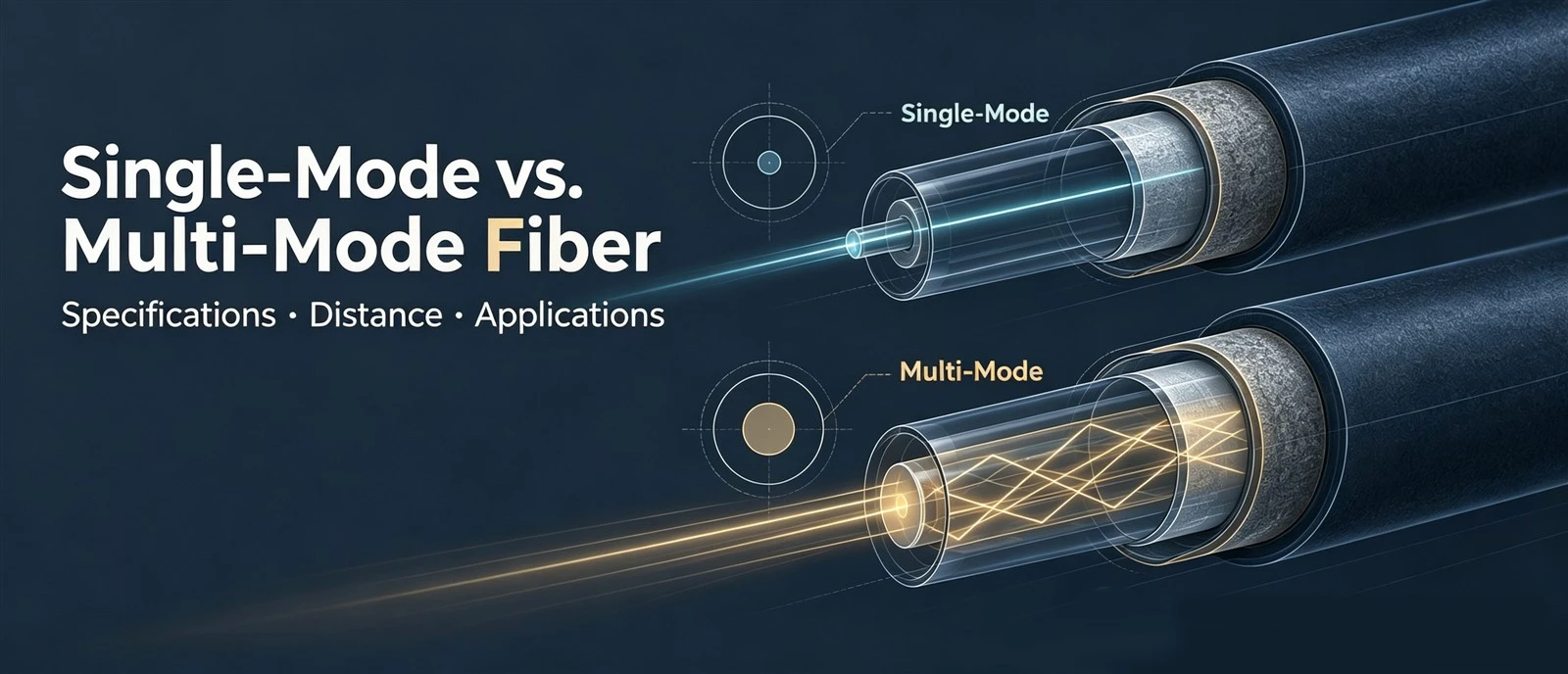
Multimode fiber has a wide core (50 or 62.5 microns) that lets light travel many paths at once, which suits short, high-speed links with cheap light sources. Singlemode fiber has a narrow 9-micron core that keeps light on one path, which reaches tens of kilometers and supports more wavelengths. Everything else in the comparison follows from those two facts.
Start with the construction, because the two cables look identical from the outside. Both have a glass core surrounded by 125-micron cladding, the outer glass layer that traps light inside. The slash notation on every datasheet tells you both numbers: 9/125 µm means a 9-micron core inside 125-micron cladding, and that is singlemode. Multimode comes in 62.5/125 µm (grade OM1) and 50/125 µm (grades OM2 through OM5).
One label trips up even experienced buyers: the mode field diameter. A singlemode datasheet lists an MFD of about 9 to 10 microns, which is not the physical core diameter. It describes the effective size of the light beam spreading through the core, and it shifts with wavelength. Read it as a performance number, not a geometry number.
Why does the wide core lose the long-distance race? Picture the core as a corridor. A wide corridor lets people walk in many formations: down the middle, hugging the walls, everywhere in between. Each formation is one "mode" of light. A narrow corridor forces everyone into single file, which is exactly what singlemode means: only the base mode survives.
Now send a crowd of runners down both corridors at the same moment. In the wide corridor, runners near the walls travel farther than runners down the middle, so they arrive at different times even though they left together. A narrow light pulse entering multimode fiber comes out stretched and blurred. Fiber engineers call this modal dispersion, and it is the reason multimode distance ratings collapse as speed rises: the faster the data rate, the shorter the gap between pulses, and the less blur the link can tolerate.
Modern multimode fiber fights back with a trick called graded-index design. The refractive index profile bends light paths so that runners on the outer, longer routes move faster through lower-index glass and catch up with the center runners. It works, but only up to a point, which is why every multimode grade still carries a hard speed-by-distance ceiling.
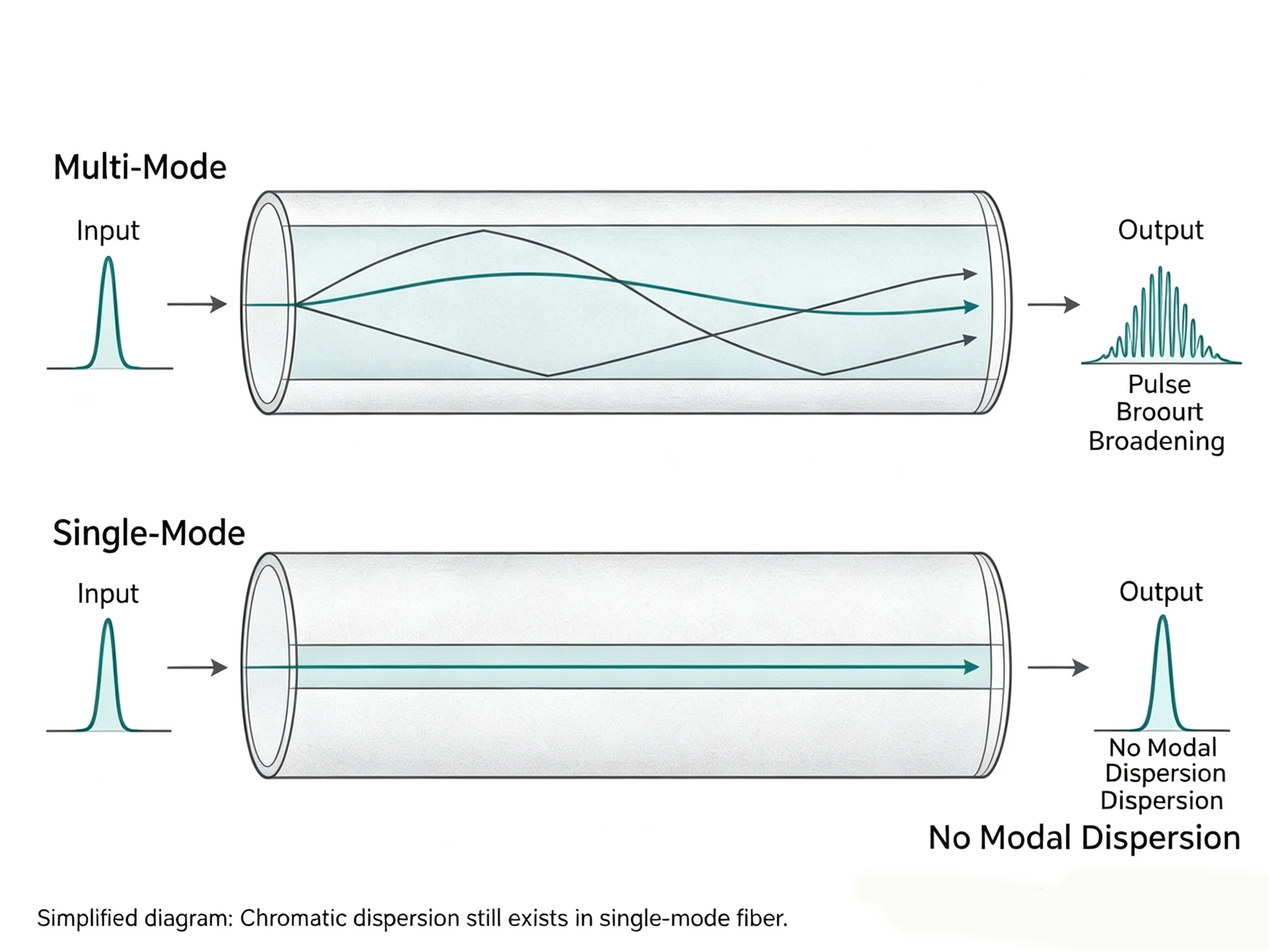
There is even a formula behind the mode count (V = 2πa·NA/λ, where a is core radius, NA is numerical aperture, and λ is wavelength). You will never calculate it in the field, but it explains the pattern: bigger cores, bigger numerical aperture, and shorter wavelengths all allow more modes.
Singlemode avoids the whole problem. One mode means no arrival-time differences between modes, so pulses stay sharp for kilometers. That said, singlemode is not "zero dispersion": it still answers to attenuation, chromatic dispersion, polarization mode dispersion, connector loss, and the transceiver's own limits.
Last myth to clear up here: singlemode does not mean faster. A 1G singlemode link runs at 1G, and a 100G multimode link runs at 100G. The fiber sets the propagation conditions and the reach; the two transceivers at the ends set the speed. Keep that in mind for every choice in this guide. For the deeper physics of core size, mode count, and light sources, our core size and light source physics guide expands everything this section compressed.
2.How Do You Distinguish Multimode From Singlemode by Sight?
Work through four checks in order: read the printed legend on the jacket, read the transceiver it serves, treat jacket color as a hint rather than a verdict, and check connector polish colors separately. The printed legend is the only check that settles the question on its own.
Step one: the legend. Every quality patch cord carries print along its jacket, and it is self-describing. "9/125 OS2" is singlemode, cabling grade OS2. "50/125 OM3" is laser-optimized multimode, grade OM3. "62.5/125 OM1" is the legacy multimode. If a cable only shows a part number, look it up in the manufacturer datasheet before you trust it with a link.
Step two: the transceiver. The module plugged into the far end of the cord is a witness that never forgets. Labels containing 850 nm, SX, or SR point to multimode. Labels with 1310 nm, LR, ER, or ZR point to singlemode, with ER and ZR belonging to the longest reaches. One exception is worth memorizing: 1000BASE-LX is a singlemode optic that can run over multimode fiber through a special mode conditioning cord, so always confirm the Fiber Type line in the datasheet.
Step three: color, the hint that everyone mistakes for an answer. Under the TIA-598 fiber color code that the Fiber Optic Association documents, the conventions are:
|
Jacket Color
|
Usual Fiber Type
|
|
Yellow
|
Singlemode (OS1/OS2)
|
|
Orange
|
Multimode (OM1/OM2)
|
|
Aqua
|
Multimode (OM3/OM4)
|
|
Violet
|
Multimode (OM4, alternative)
|
|
Lime green
|
Multimode (OM5)
|
Outdoor cables wear black jackets that follow no indoor convention at all, industrial cables get their own color logic, and custom cords can be dyed to match a brand. Color rules out nothing. We have seen yellow-jacketed OM3 cords built for a "premium" look, and we have seen buyers pay for that mistake twice: once for the wrong cord, once for the troubleshooting day.
Step four: connector housing colors, which answer a different question. Blue and green housings mark UPC and APC polish styles, not fiber types. Both singlemode and multimode come in LC, SC, and MPO bodies, and both fiber types use UPC and APC polishes. Never mate UPC to APC: the angle mismatch causes high return loss, high insertion loss, and it can physically damage the ferrule ends. The full polish comparison lives in our APC vs UPC polishing guide.
|
Connector Housing
|
What It Really Means
|
|
Blue
|
UPC polish (either fiber type)
|
|
Green
|
APC polish (either fiber type)
|
|
Beige
|
Usually multimode 62.5/125
|
|
Black or gray
|
Usually multimode 50/125 or OS2 per vendor
|
And a safety rule that belongs in every fiber guide: never stare into a connector or into the fiber itself to check for light. Communication wavelengths are invisible, so a fiber that looks dark can still be carrying laser power that harms your eyes. Kill the source, then inspect with a power meter or a scope.
When all four checks agree, you are done. When the printing has worn off and the transceiver is gone, skip to the wavelength test in the next section. For the product side, our singlemode and multimode patch cords carry grade print along every meter, and our fiber optic connector types page shows the full housing range.
3.How Can You Verify Fiber Type With a Quick Test?
Shoot light through the cable at two wavelengths and watch which one gets through. Multimode passes 850 nm easily and rejects 1310 nm; singlemode does the opposite. A light source, a power meter, and two minutes settle what the jacket no longer can.
This works because each fiber type is engineered for its own wavelength windows. Multimode plants its flags at 850 nm and 1300 nm. Singlemode plants its flags at 1310 nm and 1550 nm, the windows where the ITU-T G.652 standard caps fiber attenuation at 0.36 dB/km and 0.22 dB/km respectively. At the wrong wavelength, a fiber does not just lose a little; it can lose the signal entirely.
The two-minute procedure:
1. Connect the light source to the power meter through a short reference jumper and record the reference power P0.
2. Inject the test cord at 850 nm and read the received power P1. Loss equals P0 minus P1.
3. Repeat at 1310 nm.
4. Low loss at 850 nm with high loss at 1310 nm means multimode. The reverse means singlemode.
If you would rather read than radiate, the transceiver label remains the fastest witness, and our transceiver types from 1G to 800G guide decodes the whole naming system, from SX and SR through LR, ER, ZR, and the parallel SR4/SR8 families.
Two more instruments add confirmations. An OTDR, the tool that fires a pulse down the fiber and maps the echoes, leaves a signature in its trace: multimode traces show strong backscatter and a steep attenuation slope, while singlemode traces run flatter and reach much farther before the noise floor swallows them. And on a crowded ODF frame where ten look-alike cords share one patch panel, many light sources offer a modulated output at 270 Hz, 1 kHz, or 2 kHz. Tune the power meter to your tone, and only the cord actually connected to your source responds. It is a fiber finder, not just a power meter.
One caution on our own factory practice: the wavelength test tells you the fiber category, not the grade. A 50-micron cord that passes at 850 nm could be OM2, OM3, or OM4. When the grade matters for your distance plan, trust the datasheet or the print, and when neither exists, treat the cord as the lowest grade and re-plan the link, or simply replace it. Testing every reel on calibrated instruments, as our CNAS-accredited lab does with optical transceiver modules and cords alike, removes the guesswork at the source.
4.Which Distances and Speeds Can Each Fiber Really Support?
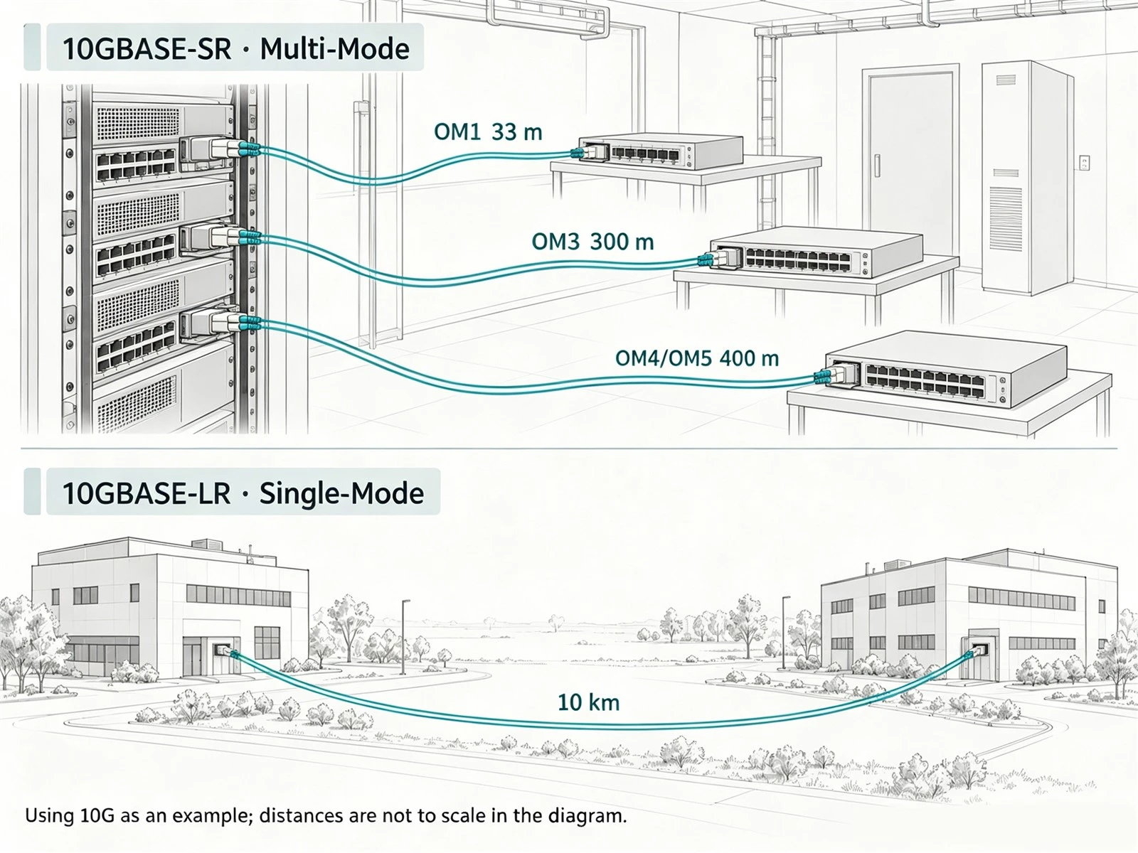
Multimode covers in-building distances: 10G to 300 m on OM3 and 550 m on OM4/OM5. Singlemode covers everything longer, 10 km and beyond on standard LR optics. As speeds climb, the multimode ceiling pulls closer, from hundreds of meters at 10G to roughly 50 m at 800G.
Distance ratings are bandwidth ratings wearing a different label. Every multimode grade carries a modal bandwidth figure in MHz·km, a distance budget for high frequencies. Here is what each grade promises at its 850 nm operating wavelength:
|
Grade
|
Core
|
Bandwidth (850 nm)
|
Remember it for
|
|
OM1
|
62.5 µm
|
200 MHz·km
|
Legacy installs, 1G short runs
|
|
OM2
|
50 µm
|
Higher than OM1
|
Legacy expansion only
|
|
OM3
|
50 µm
|
2000 MHz·km
|
First laser-optimized grade
|
|
OM4
|
50 µm
|
4700 MHz·km
|
Current workhorse
|
|
OM5
|
50 µm
|
4700 MHz·km + 953 nm spec
|
Shortwave WDM
|
The numbers come from the grade definitions summarized in references like the fiber grade reference from Fluke Networks and Cisco's OM4 vs OM5 white paper.
One misconception deserves its own paragraph: do not divide MHz·km by distance to get your data rate. Modal bandwidth is a distance budget for signal quality, not a simple division problem. The real reach also depends on the laser, its spectral width, how the launch excites the modes, the coding scheme, the receiver, and the connector losses. Always read the reach from the transceiver datasheet and the Ethernet standard, never from a back-of-envelope division.
The standardized pairings look like this:
|
Optical Interface
|
Fiber and Wavelength
|
Standard Reach
|
|
1000BASE-SX
|
850 nm multimode
|
OM1 275 m; OM2 550 m
|
|
10GBASE-SR
|
850 nm multimode
|
OM1 33 m; OM2 82 m; OM3 300 m; OM4/OM5 400 m
|
|
25GBASE-SR
|
850 nm multimode
|
OM3 70 m; OM4 100 m
|
|
40GBASE-SR4
|
850 nm parallel multimode
|
OM3 100 m; OM4/OM5 150 m
|
|
100GBASE-SR4
|
850 nm parallel multimode
|
OM3 70 m; OM4 100 m
|
|
10GBASE-LR
|
1310 nm singlemode
|
10 km
|
|
40/100GBASE-LR4
|
1310 nm singlemode
|
10 km
|
OM1 tells the whole story in one cable. Run 1000BASE-SX over it and you reach 275 m. Swap in a 10GBASE-SR module on the same glass and the reach collapses to 33 m. The fiber did not get worse overnight. The pulses got closer together, and the blur budget ran out. This is also why "singlemode is faster" is a myth worth killing: the fiber decides propagation conditions and reach, while the transceivers decide the speed.
OM5 needs an honest paragraph too. It keeps every OM4 capability and adds a bandwidth spec at 953 nm so that shortwave WDM optics can carry several wavelengths down one core. But if both ends run ordinary single-wavelength 850 nm SR modules, an OM5 link performs exactly like OM4. OM5 is not an automatic upgrade; it is a bet on SWDM optics that never became mainstream at 400G and beyond.
And the modern ceiling: at 400G, parallel multimode optics (SR8) reach about 70 m on OM4. At 800G, multimode designs shrink to roughly 50 m, while singlemode DR-class optics hold 500 m. We detail that shift in the AI data center section below. When you plan a mixed plant, our OM1 to OM5 grades in detail guide expands each grade's history and specs.
5.OS1, OS2, G.652, G.657: What Do These Labels Actually Mean?
OS1 and OS2 are cabling performance classes; G.652.D and G.657 are fiber standards. The two label systems sit on different layers, which is why one jacket can legally carry both at once. OS2 cabling is the low-attenuation class, built on fibers such as G.652.D, and G.657 marks bend-insensitive fiber for tight spaces.
Start with the OS side, because it trips up buyers who read "OS1" and "OS2" as generations of speed. They are not. Neither number refers to gigabits; both classes can carry far more than 2G, and both print "9/125 µm" on the jacket. OS1 describes older indoor tight-buffered cabling with relatively relaxed link attenuation. OS2 describes the low-attenuation class used for campus backbones, outdoor runs, and data center singlemode trunks. New singlemode builds default to OS2.
Then the G side. The ITU-T G.652 standard defines the world's default singlemode fiber: dispersion zero near 1310 nm, usable through 1550 nm, attenuation capped at 0.36 dB/km and 0.22 dB/km on those two windows for the low-water-peak D variant. G.652.D is what most "standard singlemode" cables contain.
G.657 answers a different enemy: bending. Bend-insensitive fiber tolerates tight corners that would bleed light out of a G.652 core, which is exactly what FTTH drop cables, crowded cabinets, and indoor routing need. The G.657 bend radius comparison by FS.com sums up the subclasses: G.657.A1 tolerates a 10 mm bend radius, G.657.A2 goes down to 7.5 mm, and the A-family stays splice-compatible with G.652.D. The tighter B-family bends further still but sacrifices some compatibility, so treat B-variants as specialist fiber.
So the label soup decodes like this: OS2 tells you the link class, G.652.D tells you the fiber inside meets the standard singlemode spec, and G.657.A1 or A2 tells you the fiber inside forgives tight bends. All three statements can describe the same cable without contradiction. When you quote a project, write what the installer actually needs: the class for the cabling spec, and the fiber standard for anything routed through tight trays or panels.
6.What Does Each Option Really Cost?
Singlemode optics cost 1.5 to 5 times more than multimode optics, but singlemode cable itself is cheaper than multimode cable. Multimode wins the short-run, low-speed total cost contest; singlemode wins as distance grows or speeds hit 400G and beyond.
The confusion comes from reading one line of the quote, so split the bill into its parts.
The fiber comes first. Multimode cable costs more per meter than singlemode, because the larger core and tighter manufacturing tolerances cost more to draw. On a 50 m patch run the difference is pocket change. Across a 10 km outdoor route it compounds into real money, and it is one reason carriers never build long-haul on multimode.
The optics dominate the short-run math. Multimode transceivers run on VCSELs, inexpensive vertical-cavity lasers that tolerate the wide 50-micron target. Singlemode transceivers need precision DFB or EML edge-emitting lasers aimed into a 9-micron core. Lightera's single mode vs multimode analysis puts singlemode optics at 1.5 to 5 times the multimode price depending on data rate, and our own chip-level work explains why: we manufacture DFB and EML chips for 400G/800G/1.6T solutions, and their precision is exactly what you pay the premium for.
The catch is that the optics premium shrinks as speeds rise. High-speed optics are expensive in both camps. At 400G, an SR8 module and a DR4 module sit far closer in price than their 10G ancestors did, and the Cisco OM4 vs OM5 white paper notes that multimode's cost advantage erodes generation after generation. Run the comparison at the speed you will actually operate, not at the speed you run today.
Power draws a quieter line on the same bill. VCSEL optics sip current and shed little heat, which matters when you multiply one module by ten thousand ports. Precision singlemode optics burn more, and at hyperscale that difference shows up on the facility's power line item, not the IT budget.
Inside the rack, the whole argument changes shape. For a few meters between a server and a top-of-rack switch, the cheapest "fiber" is often no fiber at all: DACs, direct-attach copper assemblies with fixed connectors, undercut everything for short hops, while AOCs, active optical cables, buy lighter weight, electrical isolation, and a few extra meters at a modest premium. We break that layer down fully in the AI data center section below.
The pattern we see in OEM orders year after year: in-building runs under 550 m at 10G to 100G stay multimode, greenfield 400G+ goes singlemode, and nobody regrets sizing the backbone for the next generation instead of the current one. Optics turn over every few years; the cable plant lives for decades.
7.8-Fiber vs 12-Fiber MPO Cable: A Comparison
Base-8 MPO uses the same 12-position connector as Base-12 with the four center fibers removed, so every fiber in the trunk carries traffic. Base-12 keeps all 12 fibers and wins backbone density and cost per fiber. Pick Base-8 for clean 8-fiber links such as SR4, SWDM4, and DR4-class breakouts; pick Base-12 for traditional 12-fiber structured backbones.
Parallel optics made fiber count a design decision. A 100G SR4 transceiver transmits on 4 fibers and receives on 4, so a clean link wants exactly 8 active fibers. Fluke Networks' polarity guide explains the mechanical compromise: a Base-8 trunk is a 12-fiber MPO connector with the middle four positions left empty, so it plugs the same ports while abandoning the center fibers.
|
Factor
|
Base-8 MPO
|
Base-12 MPO
|
|
Active fibers per trunk
|
8, all used
|
12 (4 idle in 8-fiber use)
|
|
Polarity management
|
Simple, hard to misalign
|
Methods A/B/C, more care
|
|
Troubleshooting
|
Every fiber live, easier isolation
|
Idle cores can confuse tests
|
|
Backbone density
|
Lower
|
Higher
|
|
Cost per fiber
|
Higher
|
Lower
|
|
Best fit
|
SR4/SWDM4/DR-class direct links
|
Structured backbones, legacy 40G SR4
|
Each side has a real argument. NADDOD's fiber count explainer credits Base-8 with making every fiber earn its keep and simplifying fault-finding, since no idle cores lurk in the harness. Siemon's Base-8 vs Base-12 analysis counters that Base-12 remains the structured-cabling standard, with higher density and backward compatibility that protects older 40G SR4 investment.
Polarity is where both sides bleed. An MPO link must pair every transmit fiber with a receive fiber at the far end, and the industry's three wiring methods (A, B, and C) exist to get there. Mixing Base-8 and Base-12 components in one path without a fiber map is how "plugged in" becomes "not working" for a whole afternoon. Our factory rule: one polarity method per link, every cassette labeled, polarity tested before panels close.
Now add the confusion the SERP never mentions: connector shape, fiber count, and fiber type are three different questions. A 40GBASE-SR4 link splits 40G into four transmit and four receive lanes over 8 active multimode fibers through an MPO. A 40GBASE-LR4 link merges four wavelengths onto one singlemode transmit fiber and receives on one more, so it runs over a duplex LC. Same speed, same era, opposite connectors. BiDi optics go one further and squeeze two directions onto a single strand. Neither shape tells you the fiber type, and neither tells you the speed.
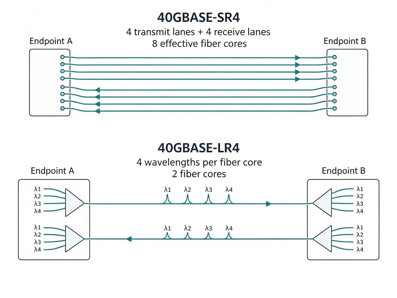
That is why a serious purchase order never says "40G fiber" or "LC jumper" alone. It states all five: the optical interface standard, the fiber category (OM or OS), the connector type, the polarity method, and the fiber count. Write all five and your supplier can quote exactly once instead of twice.
Looking forward, 800G and 1.6T parallel optics lean on 16-fiber MPO, which the same NADDOD guide maps against 8, 12, and 24-fiber variants. We manufacture MPO trunk cables in Base-8, Base-12, and MPO-16, and the selection logic never changes: match the trunk to your optics, commit to one polarity method, and leave headroom for the next speed. Our MPO cable selection guide walks the full decision.
8.Can You Mix Singlemode and Multimode Equipment?
Not directly. A fusion splice or adapter between the two fiber types loses too much light and distorts the signal, because the 9-micron singlemode core and the 50-micron multimode core barely overlap. You can bridge the two worlds with a mode conditioning cord in one direction or a media converter in both, but bridging is a migration tool, not an architecture.
What actually happens on a direct joint? The singlemode laser launches a beam narrower than the multimode core can guide cleanly, so the light excites modes in uncontrolled ways and arrives with differential mode delay the receiver never calibrated for. The link may come up or may not, and either way it is outside every specification.
Here is the trap that catches even careful crews: the link light lies. Push enough launch power through a short wrong-fiber link and the receiver still finds enough signal to light the LED. The port shows green while the link drops packets at random, runs errors under load, or fails whenever temperature drifts. A lit LED only proves that some signal arrived this second. It says nothing about bit error rate, received power margin, or stability across temperature, which are the numbers that decide whether a link is actually correct.
The legitimate bridge hardware exists and works. A mode conditioning patch cord carries singlemode fiber on one leg and multimode on the other, with a deliberate offset fusion splice inside that aims the laser at an angle into the multimode core. That skips the worst of the modal dispersion and lets a 1000BASE-LX singlemode optic serve legacy multimode plant. Two rules: it only works launching singlemode into multimode, never the reverse, and you only need it at the launch end. Omnitron's multimode-singlemode converter guide covers the hardware menu, and true two-way conversion between fiber types calls for a media converter or a switch port, not a passive cord.
Mixed core sizes cause quieter damage. Joining 50-micron to 62.5-micron multimode creates geometric and modal mismatches that quietly inflate loss, so legacy OM1 and modern OM3/OM4 should never share a link either. Dirty end faces and MPO polarity errors produce the same symptom family: intermittent loss rather than a clean failure.
Our recommendation after two decades of watching both approaches: use bridges to migrate legacy buildings, and design new builds on one fiber type per link. If you find mode conditioning cords in a new-build spec, step back and re-pick the fiber.
9.How Do You Calculate a Real Loss Budget Before You Buy?
Add up every loss source on the link: fiber length times attenuation per kilometer, plus a fixed allowance for each connector and splice. If the total stays below the transceiver's available power budget, the link has margin. If it does not, no brand of cable will save it.
The formulas fit on one line each:
Available power budget = transmitter minimum output power − receiver sensitivity
Total link loss = fiber attenuation + connector losses + splice losses + anything else in the path
A worked example makes it concrete. Say a module pair offers a 6 dB budget and the route runs 5 km of standard singlemode at about 0.35 dB/km. The fiber eats 1.75 dB. Two connection points at 0.5 dB each add 1.0 dB. Four fusion splices at 0.1 dB each add 0.4 dB. Total loss: 3.15 dB. Margin remaining: 2.85 dB.
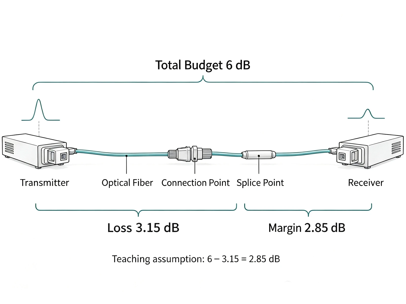
That 2.85 dB is not spending money. It has to absorb component aging, temperature swings across the year, installation deviations, and future maintenance moves. Engineers who spend the margin on paper meet it in the field as an intermittent link, and the ITU-T G.652 standard's attenuation limits are ceilings for new fiber, not promises for a decade-old route. Always run the math with the real datasheet numbers of the modules and cable you actually selected.
Multimode links play the same game with sharper numbers. At 850 nm, OM3 loses about 3.0 dB/km, per Cisco's OM4 vs OM5 white paper, so a 300 m run burns 0.9 dB before the first connector, and each connector typically costs 0.5 to 0.75 dB of budget. Multimode runs live and die by connector count, which is why the tidy panel always beats the clever splice.
One more trap hides on the other end of the scale: more light is not automatically better. Put a long-reach singlemode module on a very short link and the receiver can overload, clipping the signal into errors. Check the module's overload specification, not just its sensitivity. Modern transceivers make this easy with digital diagnostics: read the DOM/DDM screen for live transmit and receive power, confirm the port compatibility and FEC settings, and the overload question answers itself before the link ships.
When the budget and the field disagree, the usual suspects come out in order: dirty end faces first, then a stressed or over-bent fiber, then a bad splice. Our fiber loss budget calculation guide expands the method, and what a Fluke test really checks explains how certification instruments automate these checks. Keeping ODF fiber patch panels organized makes every connector in the count testable without tearing the rack apart.
10.Multimode vs Singlemode for AI Data Centers: Which One Wins?
New AI cluster backbones are converging on singlemode, while multimode retreats to short in-rack hops. At 800G, multimode optics reach only about 50 m, and AI clusters keep outgrowing that. Singlemode DR-class optics hold 500 m and beyond, which fits the spine-leaf topologies AI networks actually build.
The reach numbers explain the shift. EqualOptics' data center expansion analysis puts 800G multimode reach near 50 m versus 500 m-plus for singlemode DR optics, and AI footprints refuse to fit in 50 m. Precision OT's 2025 analysis of intra-data center connectivity documents how hyperscaler demand made 800G optics mainstream, with singlemode as the medium carrying them. The FOA's data center reference adds the economics: singlemode's bandwidth and distance headroom are effectively unlimited, and its per-bit cost keeps falling with each optics generation, which is exactly what large clusters multiply.
Multimode has not vanished from AI builds; it has retreated to the layer where its economics still win. Inside the rack and across the adjacent rack, DACs (direct attach copper) and AOCs (active optical cables) dominate 2-3 m server-to-ToR hops: DACs are simplest and cheapest in-range, AOCs earn their premium with lighter cable, electrical isolation, and a few extra meters. Our DAC vs AOC for AI clusters comparison maps that layer choice by choice, and our own DAC and AOC cables cover 10G through 800G for it.
The pragmatic AI-era architecture we keep seeing win: OS2 singlemode MPO backbones between rows, DAC/AOC economics inside the rack, transceivers bought per generation instead of pre-committed, and MPO-16 trunks wherever 800G/1.6T parallel optics are on the roadmap. That is also the design philosophy behind our own end-to-end 400G/800G/1.6T transmission solutions: fiber lasts decades, so choose the medium for where the cluster is going, not where it starts.
11.So Which One Should You Choose?
Choose singlemode when the link exceeds about 550 m, leaves the building, or forms an AI-ready backbone expected to carry 400G, 800G, and beyond. Choose multimode when runs stay inside one building under 550 m, speeds sit at 10G to 100G, and transceiver budgets dominate the quote. Everything else is arithmetic on those two poles.
The whole decision compresses into one table:
|
Scenario
|
Choose
|
Why
|
|
FTTH, PON, carrier and metro networks
|
Singlemode
|
Kilometer-class reach, passive splitting, multiple wavelengths
|
|
Campus backbone between buildings
|
Singlemode (OS2)
|
Ducts and splices outlive any optics generation
|
|
Data center interconnect (DCI)
|
Singlemode
|
10 km-class reach
|
|
In-building LAN, 10G-100G, runs < 550 m
|
Multimode (OM4/OM5)
|
Cheapest optics, easy handling
|
|
Legacy multimode plant, growing traffic
|
Stay multimode
|
Rip-and-replace rarely pays below 400G
|
|
New AI or data center build
|
Singlemode backbone + DAC/AOC in-rack
|
800G-ready, distance-proof
|
|
Factory floors and substations
|
Either, by distance
|
Both are non-conductive; pick sheath ratings for the environment
|
That last row deserves its own sentence, because electromagnetic interference drives more myths than any other topic. Neither fiber type conducts electricity, so both give you galvanic isolation for free. Pick the fiber type by distance and bandwidth, then pick the sheath for the environment: flame-retardant, oil-resistant, armored, or wide-temperature ratings matter more than the core diameter there.
When the table does not settle it, run the six questions in order:
1. What data rate does the equipment actually support, and which optical interface standard?
2. How long is the longest channel, and how many connectors and splices sit in it?
3. Which OM or OS fiber does that module permit, and on which wavelength?
4. Do connector type, polarity, and fiber count match end to end?
5. Does the power budget leave real margin for aging and temperature?
6. Will the next upgrade swap modules or re-pull cable?
Answer those six and the fiber type picks itself most of the time. Two tiebreakers cover the rest. First, fiber outlives optics: a plant installed today will still be in the ceiling when 800G modules cost what 100G modules cost now, which tilts new backbones toward singlemode. Second, mixed plants are normal and manageable: singlemode backbone, multimode or DAC/AOC at the edge, colors kept honest, layers bridged by switches rather than splices.
One warning closes every consultation we run: whatever you choose, buy from a supplier who tests what they ship. Every reel test, end-face inspection, and loss budget in this guide assumes the cable matches its label. Our quality control process puts CNAS-lab verification and FLUKE DSX-8000-class testing behind every reel we ship, because a backbone decision this durable deserves data, not promises.
12.Conclusion
Multimode vs singlemode is not a faith, it is an engineering decision, and now you hold the whole checklist. Distinguish them in the field: read the printed legend first (9/125 versus 50/125 or 62.5/125), confirm with the transceiver label, treat colors as hints, and verify with a two-minute wavelength test when the printing is gone. Choose them by arithmetic: distance ceilings, a loss budget with real margin, total cost including optics, and your upgrade roadmap through 400G, 800G, and 1.6T. And remember that a green link light is not a passing grade; stability and bit error rate are.
Planning a build and want a second pair of eyes on the fiber selection? Scroll to the inquiry form at the bottom of this page. Send us your distances, speeds, and fiber counts, and our engineers will reply with a recommendation backed by free samples: 1-3 day sample shipping, factory-direct pricing, MOQ from 500 pieces, and test data with every cord.
13.Frequently Asked Questions
Q1:Can I connect singlemode and multimode fiber together directly?
No. The 9-micron singlemode core and the 50-micron multimode core barely overlap, so a direct splice or adapter causes heavy loss and uncontrolled mode excitation. Bridge the two worlds instead: a mode conditioning patch cord launches singlemode optics over multimode fiber (1000BASE-LX style, at the launch end only), and a media converter or switch port handles two-way conversion.
Q2:Is singlemode fiber always yellow?
Yellow is the industry convention for singlemode under the TIA-598 color code, not a legal requirement. Outdoor cables wear black jackets, industrial and custom cords follow vendor color logic, and yellow-jacketed multimode cords exist. Treat color as a hint, then confirm with the printed legend (9/125 = singlemode) or the transceiver label.
Q3:Why does the link light turn on even when the fiber and module are mismatched?
Short links and strong launch power can push enough light through a wrong-fiber connection for the receiver to detect a signal, so the port lights up while the link drops packets or fails under load. A lit LED only proves that some signal arrived. Check bit error rate, received power against the module's sensitivity and overload specs, and stability across temperature before trusting any link.
Q4:How far can multimode fiber actually go at 10G/40G/100G?
At 10G, OM3 reaches 300 m and OM4/OM5 reach 400 m. At 40G and 100G over parallel SR4 optics, OM3 reaches 70-100 m and OM4/OM5 reach 100-150 m. The limits come from modal bandwidth, not connector quality, so cleaning connectors will not extend them. Beyond those ceilings you need singlemode fiber or shortwave WDM optics on OM5.
Q5:Why is singlemode cable cheaper but singlemode equipment more expensive?
Singlemode fiber has a smaller core and simpler construction, so the cable draws and tests cheaper per meter. The expense sits in the optics: singlemode transceivers need precision DFB or EML lasers to focus into a 9-micron core, while multimode transceivers use cheap VCSEL chips, which is why singlemode optics run 1.5 to 5 times the price. As speeds rise, that gap narrows and the total cost comparison flips toward singlemode.