Types Of Fiber Optic Connectors: LC, SC, ST, FC, MPO,MTP
Jul 03, 2026
Leave a message
Fiber optic connectors are the essential components that terminate the ends of optical fibers, enabling fast, reliable, and low-loss physical connections between cables, transceivers, and patch panels. Understanding the different types of fiber optic connectors - primarily the small-form-factor LC (Lucent Connector), the push-pull SC (Subscriber Connector), the legacy twist-lock ST (Straight Tip), the threaded metal FC (Ferrule Connector), and multi-fiber MPO/MTP connectors-is crucial for designing and maintaining modern telecom networks and high-density data centers. This ultimate guide will answer exactly how to identify each connector type visually, analyze their insertion and return loss performance, choose the correct end-face polish (PC vs. UPC vs. APC), and select matching fiber optic adapters.
Pick the wrong fiber optic connector and your entire link goes dark. It sounds dramatic, but it happens every day in data centers and enterprise networks around the world.
All types of fiber optic connectors account for over 80% of all physical connections inside modern data centers. LC and SC connectors handle most of the traffic. ST and FC connectors still hold their ground in industrial and outdoor settings. And MPO/MTP multi-fiber connectors are now the backbone of every 400G and 800G deployment.
Yet many technicians treat connectors as simple plug-and-play parts. 'It's just a connector; if it fits, it works.' That mindset leads to signal loss, transmission instability, and even damaged equipment. Choosing the right connector, matching the correct end-face polish, and following proper maintenance procedures can mean the difference between a flawless link and hours of troubleshooting.
At COBTEL, we've spent over 20 years manufacturing fiber optic connectors and network cabling products for data centers worldwide.
This comprehensive guide visually maps and compares all major types of fiber optic connectors (LC, SC, ST, FC, and MPO/MTP) by size, latch style, alignment tolerance, and speed compatibility from 1G to 800G
1. What Do the Four Main types of fiber optic connectors Look Like?
The four main types of fiber optic connectors are LC, SC, ST, and FC. LC and SC feature rectangular housings, whereas ST and FC are designed with round housings. You can rapidly distinguish them in a crowded patch panel or rack using three criteria: physical size, locking/latching mechanism, and their primary application environment.
Let's break down each one so you can identify them on sight, even in a crowded equipment rack.
LC Connector (Lucent Connector)
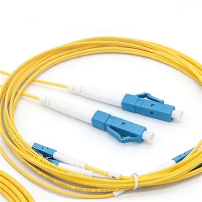
The LC is a small-form-factor (SFF) connector utilizing a 1.25mm ceramic ferrule - half the size of standard 2.5mm connectors. It features an internal spring latch that clicks audibly when fully locked into place. LC connectors are highly favored in high-speed, high-density environments such as 10G, 40G, 100G, 400G, and 800G transceivers where space is restricted.
SC Connector (Subscriber Connector)
The SC is a standard-sized connector featuring a 2.5mm zirconia ceramic ferrule and an external plastic push-pull coupling latch.You need to press the outer clip to release it. It is engaged by pushing and released by pulling the outer shroud. Popular in 1G and below enterprise networking, Fiber-to-the-Home (FTTH) subscribers, and older telecommunication distribution boxes.
ST Connector (Straight Tip)
The ST connector is round and utilizes a metal or plastic bayonet-style twist lock (quarter-turn) with a 2.5mm ferrule. It is highly secure and resistant to accidental disconnects, making it a legacy favorite in older Local Area Networks (LANs), security surveillance systems, and industrial automation.
FC Connector (Ferrule Connector)
The FC is a round connector with a threaded screw-on lock mechanism, featuring a heavy metal housing and a 2.5mm ceramic ferrule. Its threaded coupling prevents vibration or shock from loosening the alignment, making FC connectors the preferred choice for telecom backbone links, outdoor base stations, and harsh high-vibration environments.
Quick identification summary: Two square (LC is small, SC is medium) and two round (ST is bayonet twist, FC is threaded screw). By verifying size, latch style, and application context, technicians can prevent installation errors instantly.
2. What Are the Performance Differences Between LC and SC types of fiber optic connectors?
LC connectors offer slightly lower insertion loss (≤0.2dB for premium units), support speeds up to 800G, and take up half the panel space of SC connectors. SC connectors provide easier handling, broader compatibility with legacy 1G equipment, and better cost-effectiveness for low-speed links.
Beyond appearance, LC and SC differ in four core performance dimensions. These differences directly determine which connector belongs in your network.
Ferrule Material: Both Use Ceramic, But Precision Varies
Premium LC and SC connectors both use zirconia ceramic ferrules. This material offers high hardness, excellent wear resistance, and precise fiber core alignment. The difference lies in tolerance. High-end connectors achieve concentricity error ≤0.3μm, while standard-grade units reach ≤0.5μm.
Here's a practical tip we've learned from experience: because LC's ferrule diameter is smaller (1.25mm vs 2.5mm), it demands tighter manufacturing precision. If you buy low-quality LC connectors with poor ferrule accuracy, insertion loss spikes and fiber optic loss accumulates quickly. We've seen this lesson play out the hard way.
Insertion Loss: Both Excel, LC Edges Ahead
Insertion loss measures how much signal a connector absorbs. Lower numbers mean better quality. Premium LC connectors achieve ≤0.2dB, while premium SC connectors reach ≤0.25dB. Standard versions of both types stay at or below 0.3dB.
For a practical example: at 100Gbps, an LC connector with 0.2dB loss and an SC connector with 0.3dB loss will show roughly a 10% signal strength difference after 100 meters. That gap may seem small, but in long-distance links with multiple connection points, these small losses add up and threaten transmission stability.
Plug/Unplug Lifespan: Both Meet Daily Demands
Both LC and SC connectors handle 1,000+ insertion cycles. Premium products can reach 2,000 cycles. In real-world maintenance, LC connectors tend to perform better in frequent plug/unplug scenarios due to their spring-loaded latch design. For most installations, neither type will wear out under normal use.
Speed Compatibility: LC Goes Faster
LC connectors support 10G, 40G, 100G, 400G, and 800G optical transceivers due to their compact size and precision. SC connectors, with their larger footprint, mainly serve 1G and below. This is why data center core switches use LC interfaces, while residential fiber-to-the-home connections typically use SC.
Parameter
LC Connector
SC Connector
Ferrule Diameter
1.25mm
2.5mm
Insertion Loss (Premium)
≤0.2dB
≤0.25dB
Insertion Loss (Standard)
≤0.3dB
≤0.3dB
Plug/Unplug Lifespan
1,000–2,000 cycles
1,000–2,000 cycles
Speed Support
10G to 800G
1G and below
Best For
Data centers, high-speed networks
FTTH, enterprise access layer
3. How Do You Choose Between LC and SC types of fiber optic connectors?
Follow three simple rules to choose between LC and SC: match the device port type, match the transmission speed and distance, and match the cabling density of your environment. These three principles cover every common scenario.
Principle 1: Match the Device Port
This is the most basic rule. Check what port your equipment has and use the matching connector. A 100G QSFP28 transceiver uses an LC interface, so you must use LC connectors. A 1G SFP module with an SC interface requires SC connectors. If the connector type doesn't match the port, it simply won't fit. That said, most modern SFP modules now use LC interfaces, so LC has become the more common choice even for single-fiber applications.
Principle 2: Match Speed and Distance
For 10G and above, choose LC. For 1G and below, SC offers better cost-effectiveness. If you're running high-speed, long-distance links (such as 100G over 10 kilometers), always use premium LC connectors with low insertion loss. For low-speed, short-distance links (such as 1G over 100 meters), standard SC connectors deliver excellent value.
Principle 3: Match Cabling Density
When rack space is tight and you're running dozens of fiber pairs per cabinet, LC connectors save significant space. An LC connector occupies roughly half the panel area of an SC connector. For the same fiber count, LC lets you fit more connections in less space and keep cabling organized. In standard office environments with lower density, SC connectors work well because they're easier to handle and simpler for less experienced staff.
4. Proper Handling and Maintenance to Avoid Signal Faults
Choosing the right connector is only half the job. Proper plug/unplug technique and routine maintenance prevent most signal problems in the field. Here are four operational rules every technician should follow.
1. Plug and Unplug Gently
For LC connectors, hold the connector body between your thumb and index finger. Push in gently until you hear a "click." To remove, squeeze the small latch and pull straight out. For SC connectors, press the external plastic clip first, then pull out smoothly. Never yank an SC connector without releasing the clip. We once saw a technician rip the clip off an SC connector by pulling without pressing, and the connector was destroyed on the spot.
2. Clean the Ferrule Before Every Insertion
Dust or oil on the ferrule end face increases insertion loss and can even cause complete signal loss. Before connecting, wipe the ferrule with a dedicated fiber cleaning wipe or pen. Always wipe in one direction only. Back-and-forth rubbing can scratch the ferrule surface and cause permanent damage.
3. Avoid Bending and Pulling
Leave enough slack in the patch cord behind each connector. Don't pull cables taut or let connectors sit at sharp angles. The minimum bend radius for fiber patch cords should never go below 30mm. Bending or pulling can break or loosen the fiber inside the connector housing, which leads to intermittent or total signal loss.
4. Label Everything
Attach a clear label to every connector noting the device, link, and port. For example: "LC-1: Rack A, Switch 1, Port 1" or "SC-2: Floor Distribution Box, User A, ONT." Clear labeling speeds up troubleshooting and cuts maintenance time significantly.
Common LC and SC Fault Troubleshooting
No signal after insertion: Check that the connector clicked into place. Inspect the ferrule for dirt. Verify the patch cord is intact. Try a different port on the device to rule out port failure.
High signal loss or unstable transmission: Check for scratches or contamination on the ferrule. Swap in a known-good connector. Inspect the link path for excessive bends.
5. What Are ST and FC types of fiber optic connectors and When Should You Use Them?
ST connectors use a bayonet (quarter-turn) lock and work best in legacy LANs, security monitoring, and industrial control systems. FC connectors use a threaded screw lock and excel in telecom long-haul equipment, outdoor base stations, and harsh environments with extreme temperatures or heavy vibration.
Some people assume ST and FC are outdated. In reality, these two connector types still serve critical roles in specific applications where LC and SC can't match their strengths.
Identification: One Look Is All You Need
The fastest way to tell ST from FC: ST has a bayonet (push-and-twist) lock with a notched ring, while FC has a threaded nut you screw clockwise to tighten. ST housings are typically plastic and lightweight. FC housings are mostly metal, giving them a solid, heavy feel in your hand.
Performance: Stable and Reliable for Low-Speed Links
Both ST and FC share a 2.5mm ferrule diameter (same as SC). Premium versions achieve insertion loss ≤0.3dB and return loss ≥40dB. Plug/unplug lifespan reaches 500 cycles minimum, with quality products supporting over 1,000 cycles per IEC 61754 testing standards.
There's an important difference under stress. ST's bayonet lock can loosen over time in high-vibration settings, causing signal instability. FC's threaded lock provides stronger mechanical grip, better vibration resistance, and more consistent insertion loss. This is why outdoor and industrial deployments overwhelmingly prefer FC.
Core Advantages
ST connectors offer low cost, simple operation (just a quarter turn), and broad compatibility with older optical modules and legacy equipment. FC connectors deliver superior mechanical stability and can operate reliably across a temperature range of -40°C to +85°C, handling moisture, vibration, and impact that would compromise other connector types.
Real-World Application Cases
Case 1: Factory Industrial Control System. We visited a manufacturing plant in eastern China where the PLC (programmable logic controller) system used ST connectors for 100Mbps data links. The factory floor had constant vibration and heavy dust. The client initially considered switching to SC connectors, but that would have required replacing all PLC optical modules at high cost. Instead, they kept quality ST connectors with protective sleeves. The system has run stably ever since. When they later upgraded the PLC modules, they still chose ST connectors because the bayonet lock offers better dust protection and more secure engagement than SC or LC in that environment.
Case 2: Mountain-Top 4G Base Station. Telecom base stations in mountainous central China sit on peaks with extreme temperature swings, strong winds, and rain. These backhaul links use FC connectors with single-mode fiber. The threaded screw lock prevents wind-induced vibration from loosening the connection, and the metal housing resists rain and snow corrosion, ensuring stable backhaul performance year-round.
6. Fiber Optic Adapters: The Connection Bridge of fiber optic connectors
A fiber optic adapter (also called a flange or coupler) is a bridging device that aligns and joins two fiber optic connectors end-to-end to extend or interconnect a link. Every connector type, whether LC, SC, ST, or FC, requires a matching adapter. Choosing the wrong adapter or skipping proper maintenance is a top cause of preventable link failures.
The term "flange" comes from the English word used to describe disk-shaped coupling hardware. In fiber optics, the adapter's core function is to hold two connector ferrules in precise alignment inside a ceramic sleeve, creating a stable, low-loss connection point.
Classification: Match Adapter to Connector
Adapters come in LC, SC, ST, and FC versions, plus hybrid types (such as LC-to-SC) for cross-connecting different connector families. The selection rule is straightforward: your adapter type must match your connector type. ST connectors use ST adapters. FC connectors use FC adapters. Mixing types is physically impossible since the connectors simply won't fit.
Key Parameters to Check
Don't just look at the connector type. Two critical specs determine adapter quality:
Insertion loss: Premium adapters achieve ≤0.2dB. Standard adapters stay at ≤0.3dB. For high-speed or long-distance links, always choose premium.
Return loss: Premium adapters reach ≥45dB. Standard adapters hit ≥40dB.
Material matters too. Choose metal-housing adapters for better impact resistance and heat dissipation. The internal ceramic alignment sleeve should have concentricity error ≤0.3μm for precise core-to-core alignment. Low-quality adapters with poor sleeve accuracy can increase insertion loss beyond spec and even scratch connector ferrules.
Three Handling Guidelines to Prevent Failures
Guideline 1: Mount securely. Adapters mount inside ODF frames or fiber patch panels. Tighten all mounting screws so the adapter doesn't shift or wobble. A loose adapter causes ferrule misalignment, which increases loss.
Guideline 2: Clean before connecting. The ceramic sleeve inside the adapter collects dust just like a connector ferrule. Before mating connectors, use a dedicated cleaning stick to wipe the sleeve interior in one direction. We once spent hours troubleshooting an outdoor link failure, only to discover dust inside the adapter sleeve. After cleaning, the signal came back instantly.
Guideline 3: Avoid excessive plug/unplug cycles. Frequent insertion and removal wears out both the ceramic sleeve and the connector ferrule. If you need to test often, use adapters with replaceable ceramic sleeves. When the sleeve wears out, you swap just the sleeve instead of the entire adapter, saving cost.
Common ST/FC and Adapter Fault Troubleshooting
ST signal unstable: Confirm the bayonet lock is fully engaged (quarter-turn until it clicks). Clean the ferrule. Check for vibration sources and add protective sleeves if needed.
FC high insertion loss: Verify the threaded nut is tight. Inspect the ferrule for scratches. Clean the adapter sleeve. Try replacing with a premium adapter.
No signal after adapter mating: Confirm the adapter type matches the connector. Make sure connectors are fully seated. Check for debris blocking the adapter sleeve.
Link failure in harsh environments: Inspect for water or dust ingress in FC/ST connectors and adapters. Switch to waterproof or sealed adapter and connector models.
7. What Are PC, UPC, and APC End Faces in fiber optic connectors?
PC, UPC, and APC describe the polishing shape of the connector end face. PC (Physical Contact) uses a standard curved polish with return loss ≥40dB. UPC (Ultra Physical Contact) uses an ultra-smooth dome polish with return loss ≥50dB. APC (Angled Physical Contact) uses an 8° angled polish with return loss ≥60dB. The color code is simple: blue means PC, white means UPC, and green means APC.
Many technicians encounter "SC/APC" or "FC/UPC" labels and wonder what the letters after the slash mean. That suffix identifies the end-face polishing type, which determines how much light reflects back into the fiber at the connection point.
Visual Identification: Color Tells You Everything
The industry uses strict color coding that never varies:
PC: Blue housing (common on SC, LC, FC connectors). Some older models may be black, but blue is the standard.
UPC: White or gray housing (most common on LC-UPC and SC-UPC).
APC: Green housing (universal for all APC connectors: SC-APC, LC-APC, FC-APC).
Key rule: Green equals APC. Blue equals PC. White equals UPC. This color check is the fastest way to identify end-face type in the field.
Connector labels also help. Most housings print the end-face type directly: "SC-PC," "LC-UPC," or "FC-APC." Combine the label with the color and you'll never misidentify.
End-Face Geometry: Why the Shape Matters
Each polishing type creates a different ferrule tip shape:
PC: The end face has a micro-spherical (slightly curved) polish. This allows physical contact between two mated fibers, reducing the air gap and lowering reflection.
UPC: The end face uses an ultra-precision spherical polish, achieving a smoother, more uniform surface than PC. This further reduces surface irregularities and reflection.
APC: The end face combines an 8° angle with a micro-spherical polish. This angle deflects reflected light away from the fiber core and into the cladding, where it gets absorbed instead of traveling back to interfere with the signal.
Transmission Performance Comparison
Parameter
PC
UPC
APC
Return Loss
≥40dB
≥50dB
≥60dB
Insertion Loss
≤0.2dB
≤0.2dB
≤0.3dB
End-Face Polish
Micro-spherical
Ultra-precision spherical
8° angled + micro-spherical
Color Code
Blue
White
Green
APC achieves the lowest reflection because its 8° angle sends reflected light into the fiber cladding rather than back down the core. UPC reduces reflection through ultra-smooth polishing that minimizes surface imperfections. PC, with its standard polish, produces the most reflection of the three.
In a 100G high-speed link, PC connector reflections can cause transmission errors (bit errors), while UPC or APC eliminates this problem entirely. For broadcast video (CATV) and analog signal systems, even small reflections cause visible signal interference and picture degradation, making APC the only acceptable choice.
Matching Rules: Never Mix End-Face Types
This is critical. Two matching rules must always apply: connector type must match (LC to LC, SC to SC), AND end-face type must match (PC to PC, UPC to UPC, APC to APC).
Never cross-match: PC cannot mate with APC or UPC. UPC cannot mate with APC. Mixing end-face types causes return loss to drop sharply, insertion loss to spike, and in severe cases, complete signal failure.
Same type pairs freely: SC/PC works with SC/PC patch cords. LC/UPC pairs with LC/UPC patch cords. FC/APC connects to FC/APC patch cords.
The most common matched pairs in real-world networks:
SC/PC (blue): SC-to-SC/PC patch cords for enterprise networks, monitoring systems, and medium-speed links.
LC/UPC (white): LC-to-LC/UPC patch cords for data center 10G, 100G, and 400G high-speed links.
FC/APC (green): FC-to-FC/APC patch cords for broadcast, telecom long-haul, and carrier backbone links.
LC/APC (green): LC-to-LC/APC patch cords for high-density data centers and broadcast HD transmission.
Application Scenarios
APC (green): Choose APC when signal purity is critical. This includes broadcast systems (CATV), satellite communications, telecom long-haul backbone, metro networks, and fiber optic sensing systems. Even tiny reflections degrade analog signals or corrupt sensitive sensor data.
UPC (white): Choose UPC for high-speed digital data transmission. Data centers running 10G, 25G, 100G, and 400G links all benefit from UPC's low reflection and low loss. Enterprise core networks, cloud computing centers, and 4K/8K surveillance systems also perform well with UPC.
PC (blue): Choose PC for standard, cost-sensitive deployments. Enterprise access layers running ≤1G, basic 1080P surveillance systems, temporary test links, and backup connections all work fine with PC's performance level.
Operational Notes and Fault Troubleshooting
Clean carefully: All end faces need cleaning before connection. For APC connectors, wipe along the angle direction to avoid damaging the polished surface.
Never mix colors: Green APC connectors must never mate with blue PC or white UPC, even if the connector type (LC, SC, FC) matches.
Seat connectors fully: SC and LC connectors must click. FC connectors must be threaded tight (but not over-tightened, which can crush the end face). APC connectors, with their angled alignment, produce very high loss if not fully seated.
Protect from damage: Cap all unused connectors with dust covers. Avoid dropping or bumping end faces. Store patch cords without squeezing connectors.
Common Fault Scenarios:
High signal loss, unstable link: Check for end-face type mismatch (PC mixed with APC, for example). Clean ferrules. Verify full connector seating. Inspect for ferrule scratches with a magnifier.
Severe reflection interference (low return loss): Confirm whether someone accidentally inserted a PC connector into a UPC or APC link. Replace with the correct end-face type and retest.
Connector won't fit the port: Verify connector type matches (LC port needs LC connector, not SC). Check for housing damage from impact. Inspect the port for debris.
Connector loose, intermittent signal: For SC/LC, check if the latch is broken. For FC, check if the threaded nut is loose. Replace the connector if the latch or threads are damaged.
Real-World Fault Case
One enterprise data center experienced frequent packet loss and instability after upgrading to 100G links. OTDR testing showed return loss of only 35dB, far below the 50dB standard for UPC links. Investigation revealed that the installation crew had accidentally connected blue SC-PC patch cords into a white LC-UPC link, mixing PC and UPC end faces. After replacing all patch cords with LC-to-LC UPC types, return loss recovered to 55dB and the packet loss issue was completely resolved.
8. Why Are MPO and MTP the Fastest-Growing types of fiber optic connectors?
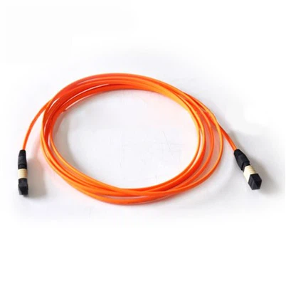
MPO (Multi-fiber Push-On) and MTP (Multi-fiber Termination Push-on) connectors pack 8 to 72 fiber cores into a single interface, boosting cabling density by up to 6x compared to single-fiber LC connectors in a 1U panel. MTP is the premium version of MPO, manufactured by US Conec with tighter tolerances, a floating ferrule, and lower insertion loss.
Traditional single-fiber connectors like LC and SC can't keep up with modern data center density. When every rack demands 400G or 800G bandwidth, plugging one fiber at a time is too slow and takes too much space. This is exactly why MPO and MTP exist.
Why Did MPO and MTP Emerge?
Traditional LC connectors require one connection per fiber. In high-density cabling, each fiber needs its own connector, adapter, and panel port. This approach eats up cabinet space, lengthens installation time, and makes cable management a nightmare.
MPO is the international standard defined by IEC 61754-7 and TIA-604-5. MTP is US Conec's registered trademark for their enhanced MPO connector with improved optical and mechanical performance, including a floating ferrule for better alignment under load and elliptical guide pins for tighter tolerance.
MPO/MTP cables use factory pre-termination technology. On-site installation drops to as little as 45 minutes. The connectors support plug-and-play deployment, reducing field workmanship risk and making maintenance faster and safer.
How to Distinguish MTP from MPO
Both are rectangular multi-fiber connectors with push-pull latches. The key differences:
Check the Appearance: Both MPO and MTP have a rectangular shape, slightly larger than simplex connectors, with a built-in push-pull latch. When plugging or unplugging, pinch the two ends of the latch and gently push or pull it. The key difference lies in the ferrule end face: The ferrule end face of the MTP connector is precision-polished to greater flatness; the standard MPO has slightly lower polishing precision, indistinguishable to the naked eye, so you need to check the markings.
Check the label: MTP connectors are marked "MTP" and typically show "Class 1" precision. Standard MPO connectors are marked "MPO" with "Class 2" precision. Fiber count is also printed (e.g., "MTP-12," "MPO-24").
Check the application context: MTP's higher precision and lower insertion loss make it the choice for 100G, 400G, and 800G high-speed links in large data centers. Standard MPO suits 10G and 40G mid-speed links or cost-sensitive edge deployments.
Check ferrule quality: MTP end faces undergo higher-precision polishing, though this difference is hard to see without instruments. For deeper technical details, see our guide on MTP cable types.
Many people use "MPO" and "MTP" interchangeably in conversation. But when specifying products for purchase, always confirm the precision class. Using standard MPO where MTP is needed can cause signal attenuation in high-speed links.
MPO and MTP Classification
MTP/MPO connectors are classified across several dimensions:
By fiber count (the most basic classification):
8-core: Common for 40G QSFP+ and 100G QSFP28 transceivers.
12-core: The most widely used configuration, covering 10G through 400G parallel links.
16-core: Designed for next-generation 400G DR4, 800G, and higher-speed applications.
24-core and above: Used for ultra-high-density backbone cabling, maximizing capacity per cable.
By gender (male/female):
Male: Has two protruding metal guide pins.
Female: Has corresponding guide holes (no pins).
Connection rule: Always pair one male with one female. Network equipment ports (such as switch transceivers) are typically male, so patch cords connecting to equipment must be female at the equipment end.
By polarity (critical for correct Tx/Rx pairing, following TIA-568 standards):
Type A (straight-through): Fiber positions match one-to-one, but key orientation reverses between ends. Needs a crossover at the patch cord level.
Type B (reversed full crossover): Fiber positions fully reversed (Position 1 to Position 12). Key orientation stays the same. This is the most common type for parallel optics.
Type C (paired crossover): Adjacent fiber pairs swap (1↔2, 3↔4). Used mainly for duplex applications, not for parallel optics.
By fiber mode: Multimode (OM3, OM4, OM5 for short-distance) and singlemode (OS2 for long-distance). Learn more about the differences in our singlemode vs multimode fiber guide.
By function: Trunk cables (MPO-to-MPO), breakout (fan-out) cables (one MPO to multiple LC/SC), and conversion cables (connecting different fiber-count MPO interfaces).
Core Advantages of MTP/MPO
Premium MTP connectors achieve per-fiber insertion loss ≤0.2dB, return loss ≥45dB, and plug/unplug lifespan ≥1,000 cycles. Standard MPO connectors reach per-fiber insertion loss ≤0.3dB and return loss ≥40dB. Notably, the total loss of a multi-fiber connector doesn't multiply by the number of cores; a 12-core MTP has roughly the same total loss as a single-core connector.
MTP/MPO supports wideband transmission from 850nm to 1550nm, working with both multimode and singlemode fiber. Large data centers use singlemode MTP for 400G long-distance backbone connections and multimode MTP for intra-rack high-speed links, all with a unified connector type.
The headline advantages:
Density up 10x or more. One 12-core MTP connector is only slightly larger than a single LC connector, yet carries 12 fibers. To carry 12 fibers with LC, you'd need 12 connectors and 12 adapters, consuming over 10x the panel space.
Installation speed doubles. Traditional single-fiber cabling for 1,000 cores could take two technicians an entire day. With MTP multi-fiber cabling, that same 1,000 cores (about 84 MTP connectors) finishes in roughly two hours.
Real-World Data Center Case
A major internet company built an ultra-large data center with 40kW per cabinet density, requiring 400Gbps non-blocking interconnection between cabinets. Using LC single-fiber connectors would have required hundreds of LC ports per cabinet, exceeding available space, with an estimated deployment timeline of 15 days.
The team chose 24-core MTP connectors paired with OM5 multimode fiber. Each cabinet needed only 16 MTP ports to deliver full 400Gbps capacity. The result: 70% reduction in cabinet space usage, deployment time cut from 15 days to 5 days, and significantly faster fault isolation during ongoing operations thanks to simple connector-level labeling.
At COBTEL, we produce MPO patch cords with factory-level precision polishing and 100% optical testing, built to support these exact high-density, high-speed deployments.
9. How Do You Select and Maintain MPO and MTP fiber optic connectors?
Select MPO/MTP connectors by matching fiber count to your transmission speed, polarity type to your link design, and precision class to your performance budget. Maintain them with gentle plug/unplug, thorough cleaning of all fiber cores, verified polarity before connection, and proper bend radius management.
MTP/MPO selection is more complex than choosing single-fiber connectors. Three dimensions matter most.
Selection Tip 1: Fiber Count by Speed Tier
10G/40G: Choose 12-core. A 40Gbps link uses 4 Tx + 4 Rx lanes, so 12 cores provide full coverage plus 4 spares.
100G/200G: Choose 24-core. A 100Gbps link uses 8 Tx + 8 Rx lanes. 24 cores leave 8 spares for future 200G upgrades.
400G/800G: Choose 48-core or 72-core. These high-density scenarios use wavelength division multiplexing and need more cores to support integrated transmission, reducing overall connector count.
As a general rule, size your fiber count for your target speed and add 10% to 20% spare capacity for future growth.
Selection Tip 2: Polarity Matching
This is the trickiest part of MPO/MTP selection. Getting polarity wrong means "transmit connects to transmit" and the link stays dark.
Type A (straight-through): Best for direct device-to-device connections, such as switch to server.
Type C (paired crossover): Best for flexible test environments. Offers the highest compatibility but costs slightly more.
Selection Tip 3: Precision Class by Budget
MTP (Class 1): High precision, low insertion loss. Choose this for 100G and above, long-distance links, and new high-density data center builds where the budget supports premium components.
MPO (Class 2): Good precision at 20% to 30% lower cost than MTP. Suitable for 10G/40G mid-speed links, edge facilities, and budget-conscious legacy upgrades.
Four Operational Guidelines
Guideline 1: Gentle plug/unplug. Hold both sides of the push-pull latch. Push in until you hear a "click." To remove, press the latch release and pull straight out slowly. Never force it. We once saw a technician yank an MTP connector sideways, breaking internal fiber cores and destroying an expensive multi-fiber cable.
Guideline 2: Clean every core. Multi-fiber connectors have many ferrule cores. One dirty core means one failed channel. Use a dedicated MTP/MPO cleaning pen. Wipe from the center of the end face outward in one direction. Then clean the device port with a cleaning stick. Connect immediately after cleaning to prevent re-contamination.
Guideline 3: Verify polarity before connecting. Check the polarity labels on both ends (Type A, B, or C) before mating. Confirm they match the link design. Label each connector and port with polarity type and location (e.g., "Type B, Rack A, Position 1") for fast reference.
Guideline 4: Respect bend radius. MTP/MPO multi-fiber cables require larger bend radii than single-fiber cables. The minimum is 40mm for static installations and 80mm for cables that move during maintenance. Leave enough cable slack at each connection point, especially near the connector boot, to prevent internal fiber damage.
Common MPO/MTP Fault Troubleshooting
Some channels have no signal: Clean the corresponding core's end face. Verify polarity matches. Try swapping the connector.
All channels have no signal: Check that the latch is fully engaged. Test on a different port. Verify that polarity isn't completely reversed.
High signal attenuation across channels: Check for excessive cable bending. Inspect end faces for scratches. Replace with a premium MTP connector or clean the port, then retest.
10. types of fiber optic connectors at a Glance: Quick Comparison
Use this reference table to compare all major types of fiber optic connectors covered in this guide.
Feature
LC
SC
ST
FC
MPO/MTP
Shape
Rectangular (small)
Rectangular (medium)
Round
Round
Rectangular (wide)
Ferrule Diameter
1.25mm
2.5mm
2.5mm
2.5mm
MT ferrule (multi-core)
Latch Type
Internal spring clip
External plastic clip
Bayonet (quarter-turn)
Threaded screw
Push-pull latch
Insertion Loss (Premium)
≤0.2dB
≤0.25dB
≤0.3dB
≤0.3dB
≤0.2dB (MTP)
Speed Support
10G to 800G
≤1G (mostly)
≤1G
≤1G
10G to 800G+
Best For
Data centers, high-speed
FTTH, enterprise access
Legacy LANs, industrial
Telecom, outdoor, harsh
High-density data centers
End-Face Options
PC, UPC, APC
PC, UPC, APC
PC, UPC, APC
PC, UPC, APC
UPC, APC
Quick selection guide:
High-speed data center (10G to 800G): LC for single-fiber links, MPO/MTP for multi-fiber parallel links.
Fiber-to-the-home or enterprise access (≤1G): SC for cost-effectiveness and easy handling.
Industrial control or legacy systems: ST for basic environments; FC for vibration-heavy or outdoor settings.
End-face type: APC for broadcast/telecom, UPC for data center digital links, PC for cost-sensitive low-speed links.
Always match: Connector type to device port. End-face type to end-face type. Adapter type to connector type.
11. Conclusion
Fiber optic connectors may look like simple plugs, but every choice you make (connector shape, end-face polish, adapter type, and multi-fiber configuration) directly affects link performance and long-term reliability.
Three takeaways to remember:
Always match three things: connector type to device port, end-face type to end-face type (never mix APC with UPC or PC), and adapter type to connector type.
Clean before every connection. Most signal faults trace back to a dirty ferrule or adapter sleeve.
Choose connectors for your future, not just today. LC and MPO/MTP are the connectors built for 400G, 800G, and beyond. Deploying them now saves costly re-cabling later.
At COBTEL, we manufacture the full range of fiber optic connectors, MPO patch cords, optical modules, and network cabling products, all backed by rigorous quality testing and over 20 years of industry experience.
Ready to find the right fiber optic connectors for your project? Fill out the inquiry form at the bottom of this page and our engineering team will review your requirements and recommend the perfect solution for your network.
12. Frequently Asked Questions
1. Can I mix APC and UPC types of fiber optic connectors on the same link?
No, you should never mix APC (green) with UPC (white) or PC (blue) connectors on the same link. Mixing end-face types causes a sharp drop in return loss, a spike in insertion loss, and can damage the ferrule surfaces. Always match end-face types exactly: APC to APC, UPC to UPC, and PC to PC.
2. What is the difference between MPO and MTP fiber optic connectors?
MPO is the industry-standard multi-fiber connector defined by IEC 61754-7. MTP is a premium version made exclusively by US Conec, featuring tighter tolerances, a floating ferrule, and elliptical guide pins. MTP achieves lower insertion loss (0.15 to 0.35dB vs 0.35 to 0.75dB for standard MPO) and longer mechanical life. All MTP connectors are MPO-compatible, but standard MPO doesn't meet MTP performance levels.
3. Which fiber optic connector type is best for 400G data center links?
For 400G parallel optics (400GBASE-SR8), use MPO-16 or MTP-16 connectors with UPC polish on multimode fiber (OM4/OM5). For 400G single-mode links (400GBASE-DR4), use MPO-12 with APC polish. LC connectors also serve 400G in duplex configurations with certain transceiver types. The right choice depends on your transceiver standard and distance requirements.
4. How often should I clean fiber optic connector end faces?
Clean the ferrule end face every time before making a connection. Use a dedicated fiber optic cleaning wipe or pen and always wipe in one direction. According to Fiber Optic Association best practices, even microscopic dust particles can increase insertion loss by 0.5dB or more and cause intermittent signal faults.
5. Do ST and FC types of fiber optic connectors still have practical uses today?
Yes. ST connectors remain the standard choice for many industrial control systems (PLC networks), legacy security camera installations, and older LAN equipment. FC connectors are still widely used in telecom carrier long-haul equipment, outdoor base stations, and industrial environments with heavy vibration, extreme temperatures, or moisture exposure. Both connector types continue to be manufactured and deployed globally.