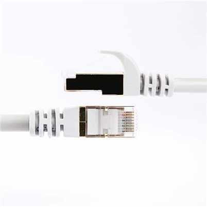
Detailed diagram of rj45 jacks and ethernet cable termination
Leave a message
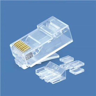
Detailed diagram of the information module and several network cable connections
The network module (also called "network slot") is mainly used to establish connections between the equipment rooms and workplaces and is generally installed on the inner wall which is not easy to be destroyed and has higher stability and durability, and can reduce the high cost caused by rectilinear obstacles routing. Network modules are generally installed on the wall, there are also desktop-mounted and ground-mounted types, mainly to facilitate the movement of computers and other network equipment, and to keep the artistic appearance of the entire cabling.
Network module production.
First of all, let's get to know the network module. This is the module mounted behind the ethernet cable socket at home, There are left and right sides, and the A and B color labels shown on the surface represent two different ways of wires being punched down, choosing any one of them is OK.
Now we start to terminate the ethernet cable, first of all, we peel off the outer jacket of the ethernet cable to expose the 4 twisted pair wires, this time you can peel the cable a little longer, to facilitate the later termination process.
Punch down the ethernet cable to the keystone jacks:
Divide the wires into two groups, following the methods of A or B labels, and stuck the wires of the corresponding color in the corresponding position of the module.
Before the termination process starts, let's get to know a bit about the punch-down tools: this is the head of the punch-down tool, and the right side of the metal is a scissor-like head that cuts off the excess first.
Now we start to terminate the patch cable, press down the module and the wires with the tool, press down hard to stick the wires inside the module, and cut off the excess wire ends.
One-to-one correspondence termination method. That is, the core wires of both two ends of the twisted pair should correspond to each other, that is, if one end of the first pinout is green, the other end of the first pinout must also be green.
This kind of twisted-pair cable is usually called a "straight-through wired cable".
However, it should be noted that the 4 twisted pairs cannot be separated, that is to say, the two core wires of each twisted pair are usually arranged next to each other.
(2) 1-3, 2-6 crossover termination method. Although the twisted pair has 8 core wires composed of 4 pairs. In fact, in the network transmission, only four of them are used, namely, the first, the second, the third, and the sixth pinout of the modular plug, they play a role in receiving and sending signals respectively. The core wire arrangement rule of crossover wired cables is as follows: the first pinout of one end is connected to the third pinout of the other end, the second pinout of one end is connected to the sixth pinout of the other end, and the rest pinouts are connected in a one-to-one corresponding way. The cable made of this arrangement is usually called crossover wired cable.
This type of cable is generally used in the cascade of hubs (switches), connections between servers and hubs (switches), peer-to-peer computer network connections, etc.
(3) 100M termination method. This is one of the most commonly used rules for making network cables. The so-called 100M termination method means that it can meet the communication rate of 100M bandwidth. Although its termination method is also one-to-one correspondence, the color of each pinout is fixed.
Specific content: pinout 1 - orange-white, pinout 2 - orange, pinout 3 - green-white, pinout 4 - blue, pinout 5 - blue-white, pinout 6 - green, pinout 7 - brown-white, pinout 8 - brown.
From the above, we observe that not all 4 twisted pairs of the wires are arranged next to each other, the 3rd pinout, the 4th pinout, the 5th and
the 6th pinout contain 2 pairs of core wires, but the sequence has been in disorder.
This termination method is also used for connections between hubs (switches) and workstation computers, i.e. the same scope as that of the "straight-through wired cable".
The EIA/TIA wiring standards specify two wire sequences for twisted pair cables, 568A, and 568B
T568A: green-white, green, orange-white, blue, blue-white, orange, brown-white, brown
T568B: orange-white, orange, green-white, blue, blue-white, green, brown-white, brown
The difference between T568A and T568B is that the positions of wires 1 and 3, 2 and 6 are swapped.
The 100BASE-T4 RJ-45 provides rules for twisted pairs as follows.
1 and 2 are used for sending signals, 3 and 6 are used for receiving signals, and 4 and 5, 7 and 8 are bi-directional.
1, 2 Wires must be twisted, 3, 6 twisted, 4, 5 twisted, 7, 8 twisted.
In the following, we will tell you about the wall network cable socket termination.
Please see the following diagram:
Answer: Follow the B class, according to the color hint above, and punch down the core wires of the corresponding color with the crimping pliers. That's finished, and then test it by using a computer.
Termination methods of network modules and applications.
The network wiring of a home decoration project is actually somewhat the same as the construction method of wire wiring, which is concealed in the floor, wall, through the PVC pipe.
It is concealed in the floor, wall, through PVC pipe and terminated in 86 bottom box. However, the network cable is a network cable with one information point, and the middle
No renewal is allowed, and one line goes to the end. These are not difficult for the general construction team, but the difficulty is how to install the network cable start
The difficulty is how to install the interface module at the beginning and end of the network cable.
At the beginning is the installation of the "network module strip" located in the home information access box, and at the end is the installation of the RJ45 information
module. The following is a description of each.
Installation of the information module
This refers to the RJ45 information module, which meets the T-568A Super Category 5 transmission standard and is compliant with T568A and T568B
It is suitable for communication socket connection between devices and work areas. The main differences in the termination methods of the information modules are
The T568A module and the T568B module are terminated with the following internal fixed connections. The corresponding wiring sequence for the two termination methods is shown in the table below.
The wiring sequence for the two termination methods is shown in the following table.
1. Wire-typed RJ45 information module installation
The RJ45 information module has eight wire pin contacts in the front jack corresponding to the eight wires of the twisted pair; the rear two sides of each of the four tapping posts, the housing is made of polycarbonate, and there are metal clips embedded in the tapping posts to connect the wires; the RJ45 information module has eight wire pins in the front jack corresponding to the eight wires of the twisted pair.
The four wire-punching posts are located on each side of the module, the shell is made of polycarbonate, and there are metal clips embedded in the wire-punching posts to connect the wires.
A row indicates the T586A wire sequence mode and B row indicates the T586B wire sequence mode.
A row indicates T586A wire sequence mode, B row indicates T586B wire sequence mode. This is the most common RJ45 information module that requires a wire punching tool to punch the wires.
The specific production steps are as follows.
Step 1: Pull the twisted pair wire from the dark box, leaving 40 cm of wire head, and cut off the excess wire. Use a wire stripping tool
or crimping tool to strip the outer skin of the twisted pair at about 10 cm long from the wire head. As shown in the figure.
Step 2: Separate the stripped twisted-pair cores by pairs, but do not disassemble the pairs yet, only when the corresponding pairs are
only when the corresponding pair is pre-pressed into the wire punching post. Select our preferred wire sequence pattern according to the color code indicated on the information module
(Note: In a cabling system it is best to use only one line sequence mode, otherwise the connection is messed up, the network does not pass is
It is very difficult to check), the stripping place and the rear face of the module parallel, both hands slightly rotate the stranded pair, slightly force the wire into the corresponding
corresponding wire slot.
Step 3: After all pairs are pressed into each slot, you can use the 110 hitting tool (below) to press a wire
Once all pairs have been pressed into the slots, a wire core can be further pressed into the slots with the 110 wire punch (below).
To use the 110 wire tool, always cut the remaining wire with the blade facing the side of the module.
and the module is inserted vertically into the slot, vertical force impact, hear a "click" sound, indicating that the groove of the tool has been
Core pressure in place, has been embedded in the metal clips, metal clips and has been cut into the crust bite copper wire core to form a pass
Road. Here pay attention to the following two points: the blade outward - if you forget to become inward, pressed into the same time also cut off the
should have been connected to the copper wire; vertical insertion - if you hit the slant, it will make the mouth of the metal clamps open, no longer
There is the ability to bite, and hit the wire post will also be crooked, difficult to repair, the module can be scrapped. If you buy a new
good tool in the impact at the same time, should be able to cut off more than one core, if not, I impact several times, and can be unscrewed by hand
off, as shown in the figure.
Step 4: Snap the plastic dustproof sheet of the information module on the wire hitting post, and snap the wire hitting module into the information
The module will be snapped into the information panel.
2. Installation of wire-free RJ45 information module
The wire-free RJ45 information module is designed to facilitate accurate and fast termination without the need for wire tapping tools.
Instead of tapping the wire posts, there are two rows of four metal clips each inside the module, and the latching mechanism is integrated into the latching cap.
color code also marked column in the back of the locking cap, termination, cut out with scissors about 4CM of wire, according to the color code will be put into the corresponding core
corresponding slot, buckle, and then press the buckle locking cap with pliers (some can be pressed down by hand, and locked). Buckle
locking cap to ensure that the copper wire is fully terminated and prevented from sliding, the locking cap is mostly transparent, to facilitate the observation of the wire and metal clips
bite situation.
Installation of network module strips
There are two types of network module strips in the home information access box: the first is the back of the network module strip and the front of the same
The second is the more formal information module type, that is, the jack on the module bar is actually a number of RJ45 information modules.
The second is the more formal information module type, which means that the jacks on the module strip are actually several RJ45 information modules. The former is to simplify the termination of the modular strip, no need to play the module, just hit the crystal
The latter needs to be terminated with a 110 wire tool as described above for the information module, twisted pair.
Here we will only talk about the first type of network module strip is the back of the RJ45 jack termination method, the second will not
The second will not be repeated.
Loosen the two screws connecting the network module area to expose the wiring on the back of the module, and trim the Category 5 cable into the box to a length of 40 cm.
Trim the cable to a length of 40 cm, crimp on the Rj45 crystal connector and plug it into the corresponding jack on the back of the voice/data connection module.
The corresponding jack on the back of the voice/data connection module, and mark it well, so that the connection from the room information socket to the home communication voice/data connection module is completed.
This completes the connection from the room information socket to the HomeCom voice/data connection module.
The following describes the RJ45 crystal head crimping method: the above information module we play according to the T568A standard, so
So the crystal head here is also crimped according to the T568A standard.
Stripping the outer skin of the Category 5 twisted-pair cable 2 cm, twisted pairs of straight, according to the T568A standard wire sequence will be tightly parallel to each color wire
Arrange the wires closely parallel to each other in your hand, leaving about 1 cm, and cut the flat wire ends. Grasp the crystal head with your left hand and carefully place the
Good T568A standard line sequence of the network into the crystal head, note that the crystal head has a slot, only allow a core through
Note that the crystal head has a slot for only one wire core to pass through, one wire and one slot to be inserted. The right hand should be inserted as far as possible, and at the same time shake a left and right, in order to let the core inserted to the
end, and flattened at the end.
This can be seen from the end of the crystal head, if you can see the bright cross-section of all eight copper wires, it means
If you see a bright cross section of all eight copper wires, you have reached the end, otherwise pull out and start over, and you may have to trim the wires again. Once the bright cross section of all eight copper wires is visible
After the bright cross-section, you can use Rj45 crimping tool crimping that is, crimping, but also to the top of the consciousness of the clamp
wire, crimping finished, but also to see if the bright cross-section of the eight copper wires are still seen, see may not be
success.
Translated with www.DeepL.com/Translator (free version)