1. What Are Network Cables?
Network cables, also known as twisted pair cables, consists of four pairs of twisted wires and a plastic outer sheath. It is primarily used to connect terminal devices and access layer
switches over channel links of no more than 100 meters.

Figure 1: Twisted Pair Cable
The world's first network cable was invented by Alexander Graham Bell, the inventor of the telephone. However, for over a century, telephone lines did not see significant development as Ethernet predominantly used coaxial cables for data transmission. In the late 1980s, IBM introduced the Token Ring computer network system, which used 150-ohm shielded
twisted pair cables, different from Ethernet. In the early 1990s, AT&T proposed using 100-ohm unshielded twisted pair cables as a transmission medium, which became standard following the mainstream adoption of
RJ45 connectors. By the mid-1990s, with numerous manufacturers entering the market, categories such as Cat3, Cat4, and
Cat5 cables emerged. By 2018, ISO/IEC 11801 included Category 8 cabling systems. Currently, network cables are classified based on transmission performance into Cat3, Cat5e, Cat6, Cat6A, Class F (Cat7), and Cat8. They can also be divided into shielded and unshielded cables, with shielding materials structured as either aluminum foil shielded pairs, aluminum foil shielded and braided mesh total shield, or total aluminum foil shielded structure. Different network cables are used in various environments, which we will explore in detail later.

Figure 2: Building Structured Cabling
2. Types of Network Cables
Let's delve into the different types of network cables: Cat3, Cat5e, Cat6, Cat6A, Class F (Cat7), and Cat8.
Category 3 (Cat3):
Cat3 cables consist of a single pair of twisted wires with a conductor diameter of 0.5mm (±0.01mm). They have a transmission bandwidth of 16MHz and a maximum transmission speed of 10Mbps, with a maximum cabling length of 100 meters. These cables are mainly used in telephone voice systems.
")
Figure 3: Category 3 Cable (Also Known as Telephone Wire)
Category 5e (Cat5e):
Cat5e cables are made up of four pairs of twisted wires, with a conductor diameter of 0.5mm (±0.01mm). They have lower attenuation and crosstalk compared to Cat5 cables and have thus fully replaced the latter. Cat5e cables support a maximum bandwidth of 155MHz and transmission speeds up to 1000Mbps (1Gbps) over distances not exceeding 100 meters. They are currently used in Fast Ethernet and are gradually being phased out in favor of higher-spec cables.

Figure 4: Category 5e Ethernet Cable
Category 6 (Cat6):
Cat6 cables consist of four pairs of twisted wires with a conductor diameter of 0.57mm (±0.02mm). They support a maximum bandwidth of 250MHz and transmission speeds of 1Gbps, suitable for stable operation in Gigabit Ethernet over distances up to 100 meters. Cat6 cables exhibit excellent attenuation crosstalk ratios at 200MHz frequencies.

Figure 5: Category 6 Ethernet Cable
Category 6A (Cat6A):
Cat6A cables also consist of four pairs of twisted wires, with a standard conductor diameter of 0.57mm (23AWG, ±0.02mm). They support a maximum bandwidth of 500MHz and transmission speeds of 10Gbps. These are crucial for future baseline links and maintain stable 10Gbps transmission performance in long-duration, high-power POE environments, primarily used in 10 Gigabit Ethernet over distances up to 100 meters.

Figure 6: Category 6A Ethernet Cable
Class F (Cat7) Cables:
Cat7 cables consist of four pairs of twisted wires with a conductor diameter of 0.6mm (±0.03mm). They use an aluminum foil shielded pair and braided mesh total shield structure, supporting a transmission bandwidth of 600MHz and transmission speeds of 10Gbps. Class 7A cables, which evolved from Class F, support up to 1000MHz. On July 30, 2002, Siemon Company's TERA Class F connectors were officially chosen as the standard non-RJ type industrial interface for Class F cabling products. Since Class F systems use non-RJ45 connectors, they are not backward compatible with Cat5e and Cat6 systems. Thus, TIA introduced Cat6A in 2006, providing similar 10Gbps performance and RJ45 compatibility, leading to limited adoption of Class F systems, mainly in Northern Europe, with Cat6A being more prevalent in China.

Figure 7: Category 7 Ethernet Cable
Category 8 (Cat8) Cables:
Cat8 cables comprise four pairs of twisted wires with a conductor diameter of 0.64mm (22AWG). They employ aluminum foil shielded pairs and either braided mesh total shield or single shield structures. Cat8 cables support up to 2000MHz bandwidth and transmission speeds of 25Gbps or 40Gbps over copper cabling. Permanent link lengths do not exceed 24 meters, with channel lengths up to 30 meters. Mainly used in data centers, ISO/IEC 11801:2017 defines Cat8 transmission performance, further classified into Class I and Class II. TIA 568.2-D also defines Cat8.1 and Cat8.2, where Class I/Cat8.1 cables typically use aluminum foil shielded pairs or total shield structures with RJ45 connectors, while Class II/Cat8.2 cables use aluminum foil shielded pairs with additional braided mesh or total shield structures and TERA or GG45 connectors.

Figure 8: Category 8 Ethernet Cable
Currently, COBTEL produces Cat3, Cat5e, Cat6, Cat6A, and Cat8 cables.
3. Cabling Design Solutions
It is recommended to use Cat6 cables for horizontal cabling in structured cabling designs. This is because the industry is progressing towards Gigabit (Gbps) network upgrades, and it is expected that wired networks will fully transition to Gigabit speeds in the near future. Additionally, according to the "Design Specification for Structured Cabling Systems" (GB/T 50311-2016),
structured cabling should have a lifespan of no less than 15 years. With the anticipated advancements in network technology, bandwidth upgrades are foreseeable. Therefore, using Cat6 cables not only meets current Gigabit network requirements but also facilitates future network upgrades.
 networks")
Due to the complexity of shielded cable structures and production processes, shielded cables are more expensive and challenging to install. They require grounding to prevent issues like floating grounds. Moreover, shielded cables necessitate the use of shielded connectors and
keystone modules, and the server rooms must also undergo shielding, significantly increasing installation difficulty and cost. Therefore, shielded cables are typically not recommended for general use unless required by government, military, or other entities with stringent signal security and anti-eavesdropping needs, or in environments with strong electromagnetic interference, such as hospitals and factories.
4. Structure and Materials of Network Cables
According to the latest "Polyolefin Insulated Horizontal Twisted Pair Cables for Digital Communication" (YD/T 1019-2013), network cables generally consist of conductors, insulation layers, skeletons, shielding layers, tensile cords, and jackets.
4.1 Requirements for Copper Materials
For many consumers, there are many materials used in Ethernet cables on the market, and early cable conductors used copper-clad aluminum, copper-clad iron, etc.; now, the more popular materials on the market are oxygen-free copper and pure copper. Major cable manufacturers basically use No. 1 oxygen-free copper as the conductor for
Ethernet cables.
This is because, according to the requirements of "Polyolefin Insulated Horizontal Twisted Pair Cable" (YD/T 1019-2013), the conductor of the Ethernet cable should be solid copper. Therefore, we generally refer to the conductor of the Ethernet cable as copper core or copper wire, and also call the Ethernet cable a
copper cable. According to the requirements, the specifications and performance of the copper conductors used in Ethernet cables must comply with the standards for TR soft round copper wires in "Electric Round Copper Wire" (GB/T 3953-2009). Since TR soft round copper wire is soft and suitable for drawing and processing, it meets the production requirements of Ethernet cables. Moreover, its nominal diameter is 0.02-14.0mm, which is consistent with the 10AWG (2.5mm) copper rods purchased by general cable factories. Additionally, its resistivity does not exceed 0.017241ohmmm2/m. Therefore, not all TR soft round copper wires can be used to produce Ethernet cables. According to "Electric Round Copper Wire" (GB/T 3953-2009), the materials of TR round copper wire must comply with the requirements for copper wire blanks in "Electrician's Copper Wire Blank" (GB/T 3952-2008), that is, round copper wires for electrical wires and cables, as well as electromagnetic wires, must use copper wire blanks of TU1 or TU2 grades. Because these two grades can be used for drawing, they are suitable for the production of Ethernet cables. However, only TU2 grade copper wire blanks, which can be used for hot rolling, have a resistivity not greater than 0.017241ohmmm2/m.
Thus, we can conclude: TU2 grade copper wire blanks can be used to produce Ethernet cable conductors. According to the requirements in Table 3 of "Electrician's Copper Wire Blank" (GB/T 3952-2008), the chemical composition of TU2 grade copper wire blanks is: the content of the copper-silver alloy is not less than 99.95%, and the oxygen content is not greater than 0.002%.
Based on the above requirements, we can conclude: standard Ethernet cables are very strict about the materials used, and not all materials can be used. It must be No. 1 oxygen-free copper. Because according to Wikipedia, the copper-silver alloy content of No. 1 oxygen-free copper is 99.97%, and the oxygen content is not greater than 0.003%. While the copper-silver alloy content of No. 2 oxygen-free copper is 99.95%, and the oxygen content is not greater than 0.05%, which does not meet the requirements for TU2 grade copper wire blanks.
Then, why can't pure copper meet the material requirements for Ethernet cable conductors? According to Wikipedia, copper-silver content reaching 99.5% is considered pure copper, and there is no requirement for oxygen content. Therefore, from a chemical composition perspective, pure copper materials may not necessarily meet the requirements for TU2 grade copper wire blanks.
Therefore, we can see that the conductor materials that meet the standards of the communication industry for Ethernet cables are only No. 1 oxygen-free copper. Using materials other than oxygen-free copper does not meet the requirements of "Polyolefin Insulated Horizontal Twisted Pair Cable" (YD/T 1019-2013). Moreover, the resistivity of oxygen-free copper conductors is very low. Therefore, the overall resistance of the cable is very low, and the insertion loss (IL) caused by resistance is also very low, effectively ensuring the stability of signal transmission in the cable and preventing packet loss.
Figure 12: Oxygen-Free Copper Rod
4.2 Requirements for Insulation Layer Materials
Currently, major manufacturers basically use high-density polyethylene (HDPE) as the insulation layer, because high-density polyethylene (HDPE) has excellent high and low-temperature resistance, strong mechanical resistance, high dielectric constant, good environmental stress resistance, and can meet the requirements of the "Structured Cabling System Engineering Design Specification" (GB/T 50311-2016) for a design life of not less than 15 years for structured cabling. Therefore, major cable manufacturers basically use high-density polyethylene (HDPE) as the insulation layer material for cables. However, according to the requirements of "Polyolefin Insulated Horizontal Twisted Pair Cable" (YD/T 1019-2013), the insulation layer of the cable can use polypropylene (PP), medium-density polyethylene (MDPE), and low-density polyethylene (LDPE). But why do few manufacturers use them? What are their disadvantages?
Polypropylene (PP) is a general-purpose plastic with chemical resistance, heat resistance, electrical insulating properties, and high mechanical performance. Its physical and chemical properties can meet the use requirements of cables. However, polypropylene is not cold-resistant, and it is extremely sensitive to copper ions, accelerating degradation and aging in a copper ion environment. Therefore, it is not suitable as the insulation layer material for Ethernet cables.
Medium-density polyethylene (MDPE). Medium-density polyethylene (MDPE) has better flexibility and low-temperature resistance. However, its tensile strength, hardness, and heat resistance are inferior to high-density polyethylene (HDPE). Moreover, the production difficulty of medium-density polyethylene (MDPE) is higher than that of high-density polyethylene (HDPE), and the price is also higher than high-density polyethylene (HDPE). Therefore, medium-density polyethylene (MDPE) is also rarely used as the insulation layer for cables.
Low-density polyethylene (LDPE). Low-density polyethylene (LDPE) is a soft, breathable thermoplastic polyolefin material. However, due to the use of oxygen-free copper materials for Ethernet cable conductors, the good breathability of low-density polyethylene (LDPE) will cause oxygen-free copper to oxidize, which is not conducive to the long-term use of cables. Therefore, YD/T 760 does not recommend using low-density polyethylene (LDPE).
Therefore, the insulation layer of Ethernet cables is generally made of high-density polyethylene (HDPE). The thickness of the insulation layer is: the outer diameter of the insulation should not exceed 1.5mm. The electrical requirements are to conduct a high-voltage spark test with a direct current voltage of 2kv-6kv synchronously during the extrusion process. The test result should be no breakdown.
Figure 13: High-Density Polyethylene Granules
4.3 Requirements for Protective Jacket Materials
The protective jacket, commonly known as the outer skin, serves to wrap the four pairs of wires within one space, facilitating cabling and protecting the four pairs of wires within the Ethernet cable. Currently, the materials for Ethernet cable jackets are mainly polyvinyl chloride (PVC) and low-smoke, halogen-free polyolefin (LSZH) materials.
Polyvinyl chloride is a high-molecular chemical material of vinyl chloride copolymer, which inherently possesses flame-retardant properties with a flame resistance value greater than 40 and can easily reach UL's specified flame resistance level for level wiring cables, which must meet the CM level.
CM level is a classification of UL's flame resistance levels for cables, also known as a commercial level. Its test standard is UL 1581. According to the regulations: a bundle of cables (usually not exceeding 24) will self-extinguish within 5 meters when burning.
Because PVC jackets can easily meet this level, they have always been favored by Ethernet cable manufacturers. In addition, polyvinyl chloride (PVC) can effectively insulate heat, has high resistance to chemical corrosion, insoluble in most strong acids, and has electrical insulating properties. Therefore, Ethernet cables with polyvinyl chloride (PVC) jackets still occupy a major position in the market.
Low-smoke, halogen-free polyolefin (LSZH) cables are currently more popular cables, which produce very low smoke density when burning; moreover, the material of low-smoke, halogen-free polyolefin contains very low levels of halogens (fluorine, chlorine, bromine, iodine, astatine), so it will not produce a large amount of toxic gases when burning.
However, due to the removal of halogens, which have flame-retardant properties, low-smoke halogen-free materials themselves are not flame-retardant. Low-smoke halogen-free polyolefin cables on the market are divided into non-flame retardant, ordinary flame retardant, and those that meet the international Electrotechnical Commission's flame retardant level requirements. According to YD/T 886-1997 requirements, the flame retardant level of low-smoke halogen-free polyolefin cables must meet the International Electrotechnical Organization (IEC) specified IEC 60332-1-2 flame retardant requirements. That is, a 60cm cable is required for vertical burning test, and the test result is that the burning damage length of this cable does not exceed 50cm.
So, Not All Low-Smoke Zero-Halogen Polyolefin Network Cables Meet Requirements.When purchasing low-smoke zero-halogen polyolefin
LSZH network cables, it is crucial to ensure that the cables comply with flame-retardant standards. Generally, cables that meet these standards are more expensive and are often used in hospitals, shopping malls, train stations, and large office buildings. Additionally, some foreign companies investing in China may also require the use of low-smoke zero-halogen materials.
Flame-Retardant Requirements for Cable Jackets.Since the jacket of network cables must meet flame-retardant requirements, low-smoke zero-halogen polyolefin materials are primarily infused with magnesium hydroxide and aluminum hydroxide to achieve flame retardancy in polyolefin materials such as polyethylene and polypropylene.

Figure 14: Cable Flame-Retardant Testing
4.4 Requirements for Cross Skeleton Materials
Cross Skeleton:
Also known as a cross keel, the cross skeleton separates the four pairs of wires in a network cable into different directions to reduce crosstalk. The material for the cross skeleton is also high-density polyethylene (HDPE), typically with a diameter of 0.5mm. Category 6 and higher network cables, which need to transmit data at speeds over 1Gbps, are more sensitive to signal "noise" and require higher interference resistance. Therefore, Category 6 and above network cables that do not use aluminum foil shielding will use a cross skeleton to isolate the four pairs of wires.
However, Category 5e cables and those that use aluminum foil pair shielding do not use a cross skeleton. This is because Category 5e cables, with their relatively narrow bandwidth, can meet interference resistance requirements through their twisted pair structure alone. For cables with aluminum foil shielding, the foil itself can block high-frequency electromagnetic interference, obviating the need for a cross skeleton.
Tensile Cord:
Tensile cords prevent network cables from being stretched, which could impact their performance. Currently, most manufacturers use fiberglass for tensile cords, with some using nylon cords. Data from COBTEL Laboratory shows that nylon cords can withstand a maximum tensile force of 3.5kg, while fiberglass can withstand up to 5.5kg. Thus, fiberglass can meet more diverse construction requirements due to its higher tensile strength.
4.5 Requirements for Shielding Layer Materials
Shielding Layer:
Network cables typically have two types of shielding: single-sided aluminum foil shielding and braided mesh shielding. Aluminum foil primarily blocks high-frequency electromagnetic interference. Single-sided composite aluminum foil has an L-shaped structure with a thickness of no less than 0.012mm and an overlapping rate of no less than 20%. Braided mesh shielding is made of tinned copper wires with a diameter of no less than 0.5mm, woven with a density of no less than 65%. For single-shielded cables, a layer of PET plastic film, commonly known as Mylar, is wrapped between the cable and the aluminum foil shield to prevent current flow between the cable and the metal shield, protecting the cable from damage due to excessive current.
Additionally, cables with aluminum foil shielding usually include a 0.5mm diameter tinned copper wire for grounding to drain the induced current on the aluminum foil surface. This can also protect the cable from indirect or direct lightning strikes in stormy weather. Therefore, during installation, the drain wire should be retained and connected to the shielded
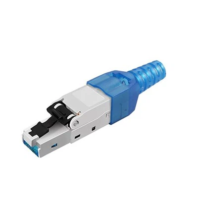
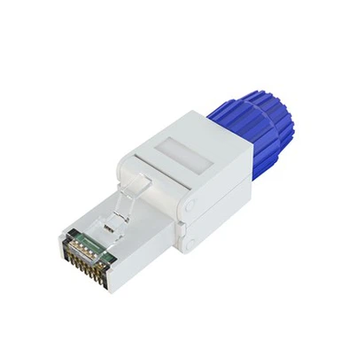
keystone jacks or the shielded shell of the
RJ45 plugs for grounding.
Figure 15: Aluminum Foil Roll
5. Process Features of Network Cables
5.1 What is Twisting?
Commercially available network cables are typically composed of four twisted pairs. According to Baidu Encyclopedia, the twisting length of network cables ranges from 14cm to 38.1cm. The primary purpose of twisting is to couple electromagnetic waves onto the two wire cores, generating a common-mode signal to reduce interference. A common-mode signal is one where the electrical signal direction is the same from the input. Since the signals transmitted in network cables are differential mode signals (where the electrical signal direction is opposite at the input), any coupled electromagnetic wave will be automatically canceled by the devices at both ends, enhancing the useful signal.
Therefore, network cables are always twisted. Without twisting, the cable's interference resistance would be very low, resulting in significant interference, including increased Near-End Crosstalk (NEXT) and Far-End Crosstalk (FEXT), which could impair signal transmission, increase error rates, and prevent terminal devices from recognizing useful signals.
Additionally, the twist lengths of the four pairs in a network cable must be uniform. If not, interference will increase, causing impedance mismatches and signal reflection, which could lead to Return Loss (RL) and signal loss.
The twist lengths of the four pairs are different to better resist interference. In Category 6 and above cables, the 12-78 pairs transmit data, while the 36-45 pairs receive data. Since the signal transmission speed in cables is approximately 67% of the speed of light, if the twist lengths were the same, signals would easily couple with interference electromagnetic waves, increasing interference and potentially failing compliance tests. Therefore, the twist lengths of the four pairs must differ to better resist interference.
Network cables also face external electromagnetic interference. Thus, in addition to pair twisting, overall twisting is necessary to resist external interference, ensuring compliance with transmission requirements for external Near-End Crosstalk (ANEXT) and Far-End Crosstalk (AFEXT).
6. Network Cable's Manufacturing Process
The manufacturing process generally includes drawing, insulation coating, cooling, untwisting and twisting, overall twisting, outer jacket coating, cooling, cutting, quality inspection, and packaging.
6.1 Drawing
The production process usually starts with drawing, where the purchased copper wire is drawn into the required copper core diameter. For example, the copper core requirement for Category 5e cables is 24AWG (approximately 0.5mm). The diameter is usually reserved with an additional 0.1-0.2mm because the copper wire will elongate and thin during subsequent processing.
Reserving a certain diameter can ensure that, upon completion of cable production, the copper core meets our manufacturing requirements. After the wire drawing process, the diameter of the copper core is tested in real-time using a diameter testing device.

Figure 16: Copper Rod Drawing Machine
6.2 Insulation Coating
The drawn copper core is then coated with insulation. High-Density Polyethylene (HDPE) and color masterbatches are mixed in a specific ratio, heated to a molten state, and extruded onto the copper core using an injection molding machine. The wire core is cooled through a long water tank and tested for diameter in real-time. High-voltage spark tests (2kv-6kv) ensure electrical insulation. Concentricity tests are also conducted, requiring the degree of overlap between the HDPE outer circle and the copper core inner circle to be above 90%.

Figure 17: Insulation Coating Production Line
6.3 pair Twisting with Backtwist
The third step is pair twisting with backtwist.The completed wire cores are paired in combinations of white-orange with orange, white-blue with blue, white-brown with brown, and white-green with green according to the production plan of the manufacturer. Twisting refers to intertwining two wires at a specified twist length, with the requirement that the twist distance is uniform throughout. In places where the twisting is uneven, the "noise" coupled onto the wire core will increase, leading to a rise in cable crosstalk, both near-end (NEXT) and far-end (FEXT). Untwisting involves counter-twisting the wire cores during the twisting process to a certain ratio to reduce the deformation of the wire cores and to prevent damage to the insulation layer due to deformation of the copper core.
After the insulation layer is applied, the wire cores form twisted pairs that will then be reeled in.

Figure 18: pair twisting with backtwist machine
6.4 Overall Twisting
The fourth step is the overall twisting into a cable. The four pairs of wires are combined and twisted together at a definite length. For Category 6 and higher unshielded twisted pair (UTP) cables, a cross skeleton is added during this step for twisting. For aluminum foil shielded twisted pair cables, the wire pairs are wrapped with the shielding layer and undergo overall twisting at this stage.
After the completion of the overall twisting, the
twisted wire pairs form the cable, which is then reeled in.

Figure 19: Overall Twisting Machine
6.5 Outer Jacket Coating
The fifth step is the coating of the external sheath. After the cables are formed, an external sheath needed to be coated. For unshielded cables, before sheathing, pulling cords are coupled with the cables and fed into the injection molding machine during transportation; shielded cables requiring overall metal shielding will have PET plastic, metal shield layers, and drain wires coupled together and fed into the injection molding machine during transport. PVC plastic granules and the required coloring agents are mixed in a certain proportion, heated to a molten state, and then extruded by the injection molding machine to form the sheath over the cable. After cooling in a long cooling trough and passing through a diameter testing device, the cables are then reeled in.

Figure 20: Outer Jacket Coating Production Line
6.6 Cutting
The finished cable is cut into lengths of 305 meters (approximately 1000 feet) or other lengths based on client requirements.The general cutting length is always a multiple of 100 feet.
6.7 Quality Inspection
Random samples of 90 meters are tested using a Fluke Networks DSX2-8000 analyzer for Permanent Link inspection.
The seventh step is quality inspection, where 90 meters of the cut wire are randomly sampled and tested with the Fluke Networks Analyzer DSX2-8000 for permanent link testing.
6.8 Packaging
Finally, the cables that pass quality inspection are packaged.
7. Conclusion
In the current market, network cables have become increasingly homogeneous. Additionally, the structure of network cables is relatively simple. As a result, many industry insiders believe that the production process for network cables does not demand high standards. Consequently, their use is often quite casual. However, in reality, the production process for network cables is quite complex, and the requirements for the construction process are also high. Therefore, only standard network cables and standardized construction can maximize the performance of network cables.