Data Center Cabling and Cable Management Standards
Jan 31, 2026
Leave a message
Preface
Effective Data Center Cabling relies on a strict set of Cable Management Standards designed to optimize airflow, prevent interference, and simplify maintenance. To answer the core requirements of data center cabling immediately: you must strictly separate power and data cables to prevent electromagnetic interference (EMI), route optical fibers vertically to ensure air intakes and exhausts remain unobstructed, and exclusively use Velcro ties-never plastic zip ties-to maintain the integrity of optical fibers. While these are the golden rules, the complexity of a data center requires specific protocols for every device layer. This article provides a comprehensive technical guide covering data center network topology (TOR, ILO, Core), detailed routing specifications for trays and cabinets, and precise labeling conventions to ensure your infrastructure is scalable and easy to manage.
I. Common Data Center Cabling & Cable Management Terminology
We will begin by defining some common data center terms. Although frequently encountered, their specific meanings are often overlooked.
Data Center Network Topology:

TOR Switch: An internal network access switch. This 1U box-style network device is equipped with 48 10G optical ports and 4 40G optical ports. The 10G ports connect downstream to server 10-gigabit ports using Active Optical Cables (AOCs), while the 40G ports connect upstream to the internal network core via MPO fiber. A single TOR switch provides server access for two cabinets.
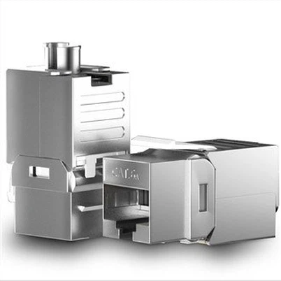
ILO Switch: The server ILO access switch, also known as the management network access switch. This 1U box-style device has 48 10/100/1000M auto-negotiating copper ports and one 1/10G optical port. The copper ports connect downstream to server gigabit ports and network device MGMT ports. The optical port connects upstream to the data center management network core using 10G multimode fiber. A single ILO switch provides access for servers and network devices in two cabinets.
Internal Network Core: A chassis-based network core device equipped with multiple 40G and 10G optical ports (configuration varies). Its 40G ports connect downstream to in-room TOR switches via MPO fiber and upstream to the Data Center Core via MPO fiber.
Data Center Core: A chassis-based network core device equipped with multiple 40G and 10G optical ports (configuration varies). Its 40G ports connect downstream to the Internal Network Core via MPO fiber. Its 10G ports connect to carrier circuits (dedicated lines) via 10G single-mode fiber and to the Unified Access/Egress device via 10G multimode fiber.
Unified Access/Egress Device: A device similar to a NAT translator, performing conversion between public and private IP addresses. A single unit has multiple 10G optical ports. These ports connect downstream to the Data Center Core via multimode fiber and upstream to the External Network Core. Additionally, they connect to a session synchronization switch via 10G multimode fiber for state synchronization between devices.
External Network Core: The core network device for the external network zone, equipped with 40G and 10G optical ports. The 10G ports connect downstream via multimode fiber to the Unified Access/Egress device, independent external network access devices, and security appliances. The 40G ports connect upstream to the External Network Border via MPO fiber.
External Network Border: The network device connecting to the Internet Service Provider (ISP), configured with 40G and 10G optical ports. The 10G ports connect upstream to ISP equipment via single-mode fiber; other 10G ports connect to security appliances via multimode fiber. The 40G ports connect downstream to the External Network Core via MPO fiber.
10G-AOC Cable: An Active Optical Cable (AOC), a fiber-like cable with integrated optical transceivers on both ends, used to connect TOR switches to server 10-gigabit ports.
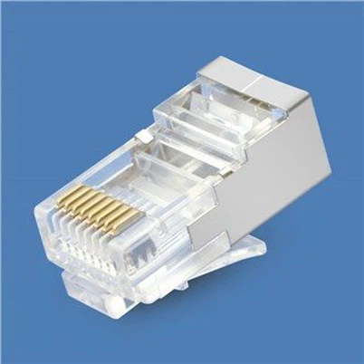
Management Network Cable: A Category 6 or 6A copper cable with RJ45 connectors, used for connections between ILO access switches and server gigabit ports or network device MGMT ports.
II. Data Center Cabling Standards
Within the same IDC and for racks of identical specifications, cabling methodology should be largely consistent to simplify day-to-day operations and maintenance (O&M). Cabling for different classes of network devices-such as core, internal network access, and management network access devices-must be orderly. Fiber and network cables must not obstruct device air intakes or exhausts, should not have excessive slack at the rack bottom, and must bear clear labels. The insertion pattern for cables on the front of network devices should be as uniform as possible, with cables neatly bundled. On the rear, power and network cables should be tidy and untangled, with power and data cables separated to present a clean, unified appearance.
1. Core Device Cabling Standards
IDC core network devices, particularly internal network cores, have numerous interconnections with TOR switches, resulting in high fiber counts. Fiber routing for core devices must be orderly, without haphazard cross-overs. Clean, aesthetic cabling within the cabinet is a primary focus of network device cabling standards.

Fibers should be routed vertically along the left or right side of the device, ensuring the path does not block air vents. Secure fibers at intervals using Velcro cable ties (note: do not use permanent plastic zip ties). Avoid over-tightening and maintain a bend radius between 100 and 130 degrees (typically ~110 degrees). Ties should allow for easy slack adjustment. All fibers must be labeled. Once plugged in, labels should remain visible. Leave sufficient service loop to facilitate easy insertion and removal.

2. Internal Network Access Cabling Standards
Internal network access switches are mounted at the top of the rack. The internal network TOR switch uses 40G MPO fiber to uplink to the internal network core and 10G-AOC cables to downlink to servers. The ILO switch uses a 1G or 10G port to uplink to the management network core and its gigabit ports to downlink to servers. Typically, two server cabinets share one internal network TOR switch and one ILO access switch (using 5-meter cables within a cabinet, 8-meter for adjacent cabinets). Each cabinet houses approximately 18 servers.

Fiber and Network Cable Routing Diagram
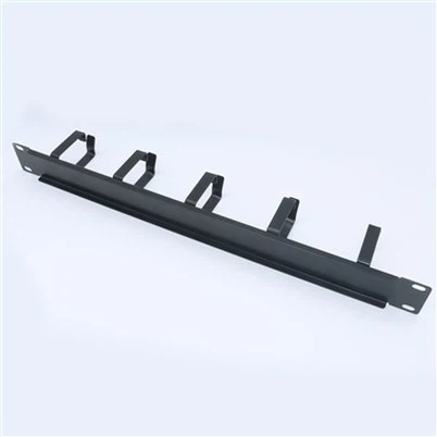
Cables from the internal network access switch are organized via cable managers. Within the manager, bundle every four network cables with a tie. Each network cable must have a unique label. The other end is routed to the server tray position within the rack. Fiber drops should not be overly long, with bend radii kept within specification. All fibers must be labeled. Use different label colors to distinguish fibers uplinked to different core devices.
3. Cable Tray Cabling Standards
All interconnection cables between network devices within the data center must be routed through cable trays (except within a single cabinet).

Cable Tray Fiber Routing Diagram
As shown, fibers and network cables within the tray must be routed separately and neatly, bundled at intervals to maintain aesthetics.
4. Cabinet Cabling Standards
A standard server cabinet primarily contains internal network AOC cables, ILO management network cables, and power cables. Consequently, cable density within a single cabinet is often significant. Each cable type should be routed and bundled along the inner side of the cabinet. As shown in the diagram below.


Use different cable colors for distinction: e.g., blue for internal network, gray for ILO, black for power. Service loops should be minimal, with cable length just sufficient to span from one PDU to the opposite one. Excess slack hinders cable management. Cabling and bundling requirements between two vertically stacked servers are shown below: [Diagram]
(To prevent electromagnetic interference, power and data cables must be separated and bundled independently.)
(To prevent electromagnetic interference, power and data cables must be separated and bundled independently.)


5. Cable Labeling Standards
Core – Internal Network TOR Labels: A single TOR uses four MPO cables to uplink to four internal network cores, respectively. Use label colors to distinguish the destination core (e.g., red, yellow, blue, green for internal network cores 1, 2, 3, 4). The label format is uniform: "Cabinet A ~ Cabinet B # Sequence Number," e.g., XX-DC-02-01~XX-DC-01-08#1. Per convention, Cabinet A denotes the core-side cabinet, while Cabinet B denotes the access-side cabinet.
Special Device Interconnection Labels: For cabling between specialized network devices (whether copper or fiber), labels uniformly follow the "Rack A ~ Rack B # Sequence Number" pattern, e.g., XX-DC-02-08~XX-DC-01-08#1.
Internal Network Access Switch – Server Interconnection Labels: Side A reflects the switch's rack position and port info; Side B reflects the server's rack position.
Example: Side A: A1-4-J-17-24-Gi1/1, Side B: J-17-01.
(Where A1-4 is the data center name, J is column J, 017 is the 17th cabinet, 24 is the 24th tray position, and Gi1/1 is the switch's GigabitEthernet 1/1 port. Side B indicates the server's rack position.)
Notes:
A standard cabinet is 48U high. One server (mounted on a tray) occupies every 2U of space. Trays are numbered sequentially from bottom to top: 01, 02, 03, ... 24.
A single cabinet has two PDU power feeds, designated Feed A and Feed B. Power labels combine numbers and letters (numbers first, letters last), with numbers always expressed as two digits. Examples: 01A-24A, 01B-24B.
Next:No Information