What is a rj45 jack?
Leave a message
1. What is a rj45 jack?

An rj45 jack, also known as an information module, category 6 module, or Ethernet module, is mainly used to connect devices and can install various low-voltage electrical sockets or connectors into various panels and wiring boards. When in use, simply insert a straight-through twisted pair cable directly into the network module to complete the connection with the Ethernet cable at the other end of the network module. Currently, network modules are generally used in internal walls, which not only protects the module from damage but also beautifies the entire network cabling environment. Due to their stability and durability, network modules are widely used in most network cabling, reducing the high costs caused by bypassing cabling for enterprises. The commonly used network modules include the 6P6C network module, 8P8C network module, RCA network module, etc.
2. Classification of network modules
In today's society, networks have become an essential tool in people's lives, and modules are widely used in copper network cabling. They are generally installed in information sockets and fixed with a card slot to connect the Ethernet cable from the switch to the Ethernet cable at the workstation end. There are mainly three types of network modules: inline couplers, toolless keystone jacks, and punch-down modules. The interface of network modules is generally RJ45 type. Below is a detailed introduction to these types of network modules.
I. Inline Couplers
Inline couplers refer to modules that directly connect twisted-pair Ethernet cables with rj45 connectors ds at both ends without the need for a wire tool. In terms of convenience, inline couplers are the best choice and are also popular. They can be connected in series to form a longer Ethernet cable. There are two special types of inline couplers: 1-to-1 inline network modules and 2-to-1 network modules.
A 1-to-1 inline network adapter is mainly used to connect two Ethernet cables and extend the length of the Ethernet cable.
Typical products include:

RJ45 single-interface dual-head Ethernet cable extender coupler
1 network module, 2 interfaces can only be connected to 1 device at the same time, eliminating the trouble of repeatedly plugging in and out of network TVs and computers.

RJ45 dual-interface dual-head Ethernet cable extender coupler
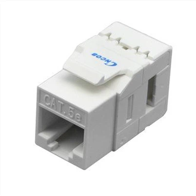
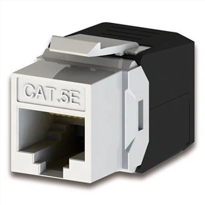
II. Toolless Keystone Jacks
Toolless keystone jacks refer to modules that do not have rj45 connectors on one end but have rj45 connectors on the other end to connect Ethernet cables. They can be punched down with or without a wire tool. Toolless keystone jacks will replace punch-down modules in the future, and they are more convenient to operate, reducing the steps of wire punching, and saving labor. They are used in the same way as punch-down modules.

Cat5e shielded (STP) toolless keystone jack
III. Punch-down Modules
Punch-down modules refer to modules that do not have rj45 connectors al heads on both ends and require wire tools to assist in wiring. They are more complicated to operate and have gradually been replaced by toolless keystone jacks.
The above is a detailed introduction to several types of network modules. Inline couplers and.
tooless keystone jacks are widely used in the docking and protection of 1000Mbps and 100Mbps Ethernet cables, and are essential tools for information technology, engineering, home, and network cabling in schools, government, banks, hotels, factories, commercial office buildings, and other environments. For more details, please visit the official website of COBTEL
3. Notes on Network Module Wiring
Before making a network information module, the corresponding wiring tools must be prepared, such as wire strippers, scissors, and wire cutters. Wire strippers are mainly used to separate the wire core and insulation layer of twisted pair cables in order to achieve the purpose of stripping. After the outer sheath is stripped off, scissors are used to cut off the torn wire. Then, the wire core is placed in the corresponding groove, and the wire cutter can help press the wire core. After reading the brief introduction to the wiring tools above, do you feel that wiring is simple? Although the wiring process is simple, there is one thing we must pay attention to.
Precautions: During the wiring process, the outer sheath of the PVC insulation layer of the cable needs to be aligned with the IDC wiring terminal to reduce the near-end crosstalk value of the wire pair. At the same time, when the cable reaches the IDC wiring terminal cutter mouth, try not to damage the twist distance of the twisted pair. If there is too much distance between the core wires at the IDC during wiring (because one pair of wires has a relatively large pitch distance among the four pairs of wires, it is easy to loosen), the margin of the near-end crosstalk NEXT will be small. If the wire pairs can be ensured not to loosen during wiring, the margin of the near-end crosstalk NEXT will increase significantly, with a 3dB difference before and after. Understanding the basic knowledge of the wiring process is necessary for the correct production of network information modules. Let's start the wiring process now.
4. Steps for Network Module Wiring
4.1. First, about 3cm away from the end of the twisted pair cable, use wire strippers to remove its outer sheath, and then use scissors to cut off the torn wire. During the peeling process, it is important to place the wire end at the blade of the wire stripper, slowly rotate the twisted pair cable until the blade cuts through the protective sheath, and then pull off the rubber sheath.

4.2 Next, insert the peeled wire into the groove of the network information module, with the sheathed part extended into the groove by about 2mm. There are two ways to insert the wire core into the slot. One is to separate the twisted pair and insert them into the slot separately. The other is to push the twisted pair apart from the wire end and insert both wire cores into adjacent slots simultaneously. Choose the method according to your own preference. In the groove, there are generally color markings and A and B markings. The A marking indicates wiring according to the T568A standard, and the B marking indicates wiring according to the T568B standard.
4.3 Taking the T568B standard as an example, first match the wire with the groove according to the icon on the module. Separate the green pair and the orange pair and insert them into the corresponding IDC wiring port on both sides, then tighten them, and then use a special single-pair end tool to press them. The pitch distance of the brown pair is relatively large, so it needs to be twisted tightly once to avoid loosening after the head cable is pulled straight. Then place the two pairs of wires according to the color marking, and use a special single-pair end tool (commonly known as a wire cutter) to press them.

4.4. After putting all the wires into their corresponding slots, double-check the order of the wires to ensure they are correct. Once confirmed, use a wire cutter to press the wires down. When pressing the wires, the wire cutter should be perpendicular to the module, with the blade facing outward. After pressing each wire core into the slot, cut off the excess wire protruding from the slot.
Note: There are certain requirements for hand gestures when pressing the wires. Correct operation can improve production efficiency and avoid the possibility of a hand injury. The correct gesture is to place the module on a flat workbench, grip the module tightly with one hand, and use fingers to press the wire. With the other hand, first place the core wires according to the color code and tighten them (you can put them in pairs or put all the core wires in place before pressing), then pick up the wire cutter, grip the middle of the handle, and make a right angle between the arm and the wire cutter. Press the wire cutter down smoothly. Note that the blade of the wire cutter should be placed outside the module, not inside.
4.5 The image below shows a network information module that has been crimped. After the module is crimped, the wiring work enters the final stage. Finally, install a protective cap on the module, and then straighten the wiring board into the slot. In this way, a network information module is completed.